
|
|
|||||||
| Forum Rules | Firearms Safety | Firearms Photos | Links | Library | Lost Password | Email Changes |
| Register | FAQ | Calendar | Today's Posts | Search |
 |
|
|
Thread Tools | Search this Thread |
 January 2, 2017, 07:34 PM
|
#101 |
|
Senior Member
Join Date: June 8, 2016
Location: Cleveland, Ohio Suburbs
Posts: 1,750
|
The power supply will not be easy. I had given some thought to using a PC PSU with a real beefy 12 Volt rail. Been awhile since I did much with PC PSUs and the use of them for other projects. If memory serves me correctly some use multiple 12 V rails as in 12V1, 12V2, 12V3 and whatever while some boasted a single 12 Volt rail. Should a 12 V ATX form factor PSU work for powering an induction heater? I would think it should. That is the only inexpensive 12 Volt high current supply I can come up with off hand. It has been about 6 years since I looked at any of the stuff.
I do have an old either Sorenson or HP bench type supply laying down at my sister's house (my mom's old house) and my brother texted me the name plate data which is 10 - 60 Volts and 0 to 18 Amps. That thing weighs over 100 Lbs. SMPS has its merits. Last I saw it run was around '97 or '98.  Using a PC ATX form factor or similar PSU should work. I am not sure how placing multiple rails on parallel will work out and I am not sure what the inrush current to a induction heater circuit will look like. Meaning will the PSU current limit and shut down before it gets going? Using 12 Volt power the current demand, even for a 500 watt induction heater comes in at just over 40 Amps. Depending on the output stage be it MOSFET or IGBT it would likely be better to run 24 Volts and that way you can use a lower current. Using an ATX or server 1U or 2U PSU may require an external small load on the 3.3 volt bus so the thing can regulate. Again, it has been years. Using a pair of MOSFETs the current draw will be a function of the voltage applied to the MOSFETs making up the load driving the coil. I plan to play around with this but not before mid February after I get the hell out of this icebox for several weeks and return. Ron |

|
|
January 3, 2017, 09:48 AM
|
#102 |
|
Junior member
Join Date: February 27, 2015
Posts: 1,768
|
Ron,
This is a little beyond my skill set, that's why I talk to electrical engineers that do this very thing. The EE tells me (and some of you trying this) it's often frequency issues. Some of these steel induction units are 'Slower' (hertz) than what they use for dense, non-ferrious metals. He informs me using a Ferrite core will help with smaller powered units. I've actually been messing with ferrite cores (c type) trying to anneal in the gap of the 'C'. (The 'Annie' and others have ferrite core attachments for brass annealing.) I'm kind of tied up with getting new product lines out for my 'Day' job and don't have a ton of time to shift gears and devote the time to this right now. My primary paycheck comes from a company that has 11 new product lines coming out, and 'New' always means 'Issues'... |
|
|
|
January 3, 2017, 09:54 AM
|
#103 |
|
Staff
Join Date: March 4, 2005
Location: Ohio
Posts: 21,063
|
Go to one of the electronics distributors, like Digi-Key or Mouser and search on single power supplies. Find one with a constant current limiting scheme rather than one that folds over and dies when the current limit is exceeded.
Once you picked out a few possibilities there and cringed at the prices, go to eBay and find a cheaper alternative based on what you've learned.
__________________
Gunsite Orange Hat Family Member CMP Certified GSM Master Instructor NRA Certified Rifle Instructor NRA Benefactor Member and Golden Eagle |
|
|
|
January 3, 2017, 10:12 AM
|
#104 |
|
Junior member
Join Date: February 27, 2015
Posts: 1,768
|
Uncle nick, I wish there was a thumbs up for that post!
I look up the 'Good' stuff on the high dollar sites (Vapor Lock at the prices), then watch eBay or like sites. I picked up power supplies for robotics, series capability up to 48 volts in 12 volt steps, $700 each retail, got all 4 for $40 (Woo-Hoo!). I did that because I had three or four 'China' power supplies that would 'Ramp Up' (that solved current spike issues), but took forever to get to full current capacity, some never did put out the stated/rated output. |
|
|
|
January 3, 2017, 12:21 PM
|
#105 | |
|
Senior Member
Join Date: June 8, 2016
Location: Cleveland, Ohio Suburbs
Posts: 1,750
|
Quote:
Over the next few weeks I have a NC trip and on my return I will stop at my sister's place in Columbus and drag out the power supply I mentioned earlier. After experimenting I will likely do as Unclenick suggested and find a compact cheap alternative. Jeephammer, your friends make an interesting point. I never gave the alloy type verse frequency much thought. I had been looking at a few induction heaters on Amazon and in my reading I managed this conclusion as to some units. Most of what I saw used a wide range of voltage for the power supply ranging from 12 to 36 Volts. The current draw and subsequent coil power was a function of the applied voltage. In other words at for example 12 Volts most would draw a current, let's call it 10 Amps. OK so power is 120 watts in an ideal world. Increasing supply voltage will result in a proportional increase on current draw so the only way to get more power is increase Vsupply or the supply voltage. That is my read so far on this stuff. So I decided to pop a few bucks and get a simple board from our little friends across the Pacific Pond in China. Considering induction heating circuits are cheap I figured why not? The images on Amazon are not quite perfect. Here is what came to my mailbox: 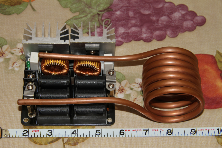 My very best guess was a 1.0" coil ID, so much for that. So why Amazon? The Internet is flooded with Induction Heater Circuits and if we look at them mos are assembled with literally a small handful of parts on a small board. While there is no shortage of board layout software out there for free the time and effort were not worth it at this point. You use layout software to design the board, then send your Gerber files to a board maker (and pray you got it right). Then get your boards and stuff with parts..... you can see where this is going. I think I paid about thirty something bucks for the pictured board. There were cheaper but lowered power for much less. This brings us to I do not have a clue how much power or at what frequency is needed to anneal brass? But for thirty or forty bucks I can experiment a little. Electronics or actually electrical engineering put beanies and weenies on the table for 40 years and got the kids through school. Today everyday can be a range day but Ohio winters do suck! After I drag an old friend in NC up here to house (and dog) sit the wife and I are out of here for a few weeks. When we get back I will have more time to play around with this. I figure the PSU will be the highest cost item in the lot. I need to look at the board I have, find the mosfet gates and think about if that is the place to add a timer function. Also, the coil is part of determining the oscillator frequecy. I should measure the inductance of the coil and then fabricate a new one of 1/4" copper tubing but smaller ID. Ron |
|
|
|
|
January 3, 2017, 01:34 PM
|
#106 |
|
Member
Join Date: December 12, 2016
Posts: 23
|
This was what I had in mind:
https://www.amazon.com/gp/aw/d/B001U...A2UY6FUW5VZE1P I think I'll run 2 of them in series to get 24v 1000w max. From what I understand to run them that way I would need to clip the earth ground on one and keep the cases isolated from each other. I was hoping that would be plenty to power the 1000watt induction heater from amazon that Jeep hammer had linked earlier on this thread. The three of you are certainly more knowledgeable than myself in this department so I would appreciate any input. Sent from my SM-G930P using Tapatalk |
|
|
|
January 3, 2017, 01:59 PM
|
#107 |
|
Senior Member
Join Date: June 8, 2016
Location: Cleveland, Ohio Suburbs
Posts: 1,750
|
Something you need to watch with a series configuration of ATX or similar power supplies. The ground is a common ground. If you measure from PSU common (black wires) to line input ground they are common to each other. Short of using an isolation transformer and eliminating the third wire ground I am not sure ATX type PSUs can be placed in a series configuration. Placing the low of the second supply in series with the high of the first may result in a dead short of the first. I may have this all wrong as it has been quite some time but you may want to be sure before investing in a few PSUs only to find it won't work. I see it as ATX output ground is common to ATX input ground (chassis ground) so thinking it would not work.
Ron |
|
|
|
January 3, 2017, 08:10 PM
|
#108 |
|
Junior member
Join Date: February 27, 2015
Posts: 1,768
|
Ron, the inverter type power supplies can be a pain...
Instead of computer power supply, I finally went with a robotics type (transformer/cap) high amperage power supply, and that allowed me to make the first & largest long/oval coil 'Rail/Conveyor' type annealer. Doesn't work like I wanted, and cooked everything that got close to it, but it laid the ground work for this latest project. I haven't messed with a bunch of the small China units in a while. Mine look pretty much like yours, and they had a TON of them for cheap. I will tell you, the mosfets aren't high quality (China made, go figure...) I've killed a couple, still have like 8 left. With the rail type, I just need to redesign the conveyor to not heat up as much (mostly brackets) and run the cases considerably faster! Might have went too far with the 'High Power' end of things... |
|
|
|
January 3, 2017, 08:23 PM
|
#109 |
|
Junior member
Join Date: February 27, 2015
Posts: 1,768
|
Kris, from experience here...
If you want to anneal in about 1.5 seconds or less and reach 750*F with no issues, Use a ferrite 'C' in the coil. Removes the issues with slow/whole case heating when using one of the server type power supplies like you have. If you can't find a 'C', start with a 'O' ring and a Abrasive jig saw or reciprocal saw blade, cut the notch just wide enough for you biggest case neck. Tile saws work pretty well, but I lent mine out between first version and latter versions. I like leaving about 1/8 or 3/16 inch on each side of the case TAPER. The magnetic field will get into the shoulder without going too far. This is ceramic you are working with, so fine grain abrasive and don't use a bunch of pressure. I cut my last try (last try because it works very well) I cut the sides of the slot at the same angle as common case tapers. Works with the common rimless brass that we load the most of, from .22 to .30 caliber cases. Slightly tight for .30, slightly loose for .22, just spot on for the 6mm family of cases. I'll make angled openings for everything sometime, this was a proof of concept and it just turned out to work well. |
|
|
|
January 3, 2017, 08:27 PM
|
#110 |
|
Senior Member
Join Date: June 8, 2016
Location: Cleveland, Ohio Suburbs
Posts: 1,750
|
For some reason the home brew versions were popular in an old electronics forum I still semi frequent. Rather than MOSFETs the better choice would likely be IGBT modules but when we depart the Chinese stuff things begin to get expensive. I wasn't too keen on the Computer PSU thing but won't discourage anyone trying it. I do plan to drag that old beast I have in my sister's basement up this way within a few weeks. The most common failure I have seen is exactly what you mentioned, Chinese MOSFETs are not quite known for being robust brutes.
When we get back from a February trip I'll get more into it. Ron |
|
|
|
January 3, 2017, 08:53 PM
|
#111 |
|
Junior member
Join Date: February 27, 2015
Posts: 1,768
|
Cool! I look forward to it!
China made power supplies for computers, LED lights, etc. were problematic. Either wouldn't produce rated outputs, slow ramp up time came in handy, but when it takes 10 seconds to top out, issues arise. Ferrite core to collect & focus the fields works pretty well, But it's a 'Patch' for an under powered unit. China induction units have WAY too big of coils, the closer the oil comes to the brass the better off you are. Fiberglass wrap keeps brass, or coil loops from contacting directly, and sets about perfect off set from the coils. What I'm being told is, when you change coil length, there are changes to be made. With the China units it's a resistor value. The biggest problem I have is an Ocilliscope is needed to determine what resistor value is needed... I'm being told this, I don't have hands on experience with it (yet), but when I get time the old 'O'scope is coming off the shelf and I'm going to see... The EE that's been right on everything so far skimmed over this, haven't got indepth or tested it, but it sank in and it's a priority when I get back to this... The EE suggested a variable resistor, which is a really good idea while working this out. Once specification are worked out, single value resistor (easier, cost savings, nothing to screw up for DIY builder). Tomorrow is cooked, going to spend about 6 hours from my paycheck job to pick up about 5,500 pounds of 5.56 mil brass. The Government End User Certificate FINALLY came in and tomorrow is the only day for another month I have to pick them up. Bad news, it's a day I shouldn't take off and 5 hour drive round trip, The good news, it's close to half million once fired brass. |
|
|
|
January 3, 2017, 09:38 PM
|
#112 | |
|
Senior Member
Join Date: June 8, 2016
Location: Cleveland, Ohio Suburbs
Posts: 1,750
|
Quote:
Ron |
|
|
|
|
January 3, 2017, 10:38 PM
|
#113 |
|
Member
Join Date: December 12, 2016
Posts: 23
|
Jeep hammer,
Do you have any pictures or links to a ferrite c core coil? I'm having trouble picturing your meaning. Sent from my SM-G930P using Tapatalk |
|
|
|
January 4, 2017, 06:01 AM
|
#114 | |
|
Senior Member
Join Date: June 8, 2016
Location: Cleveland, Ohio Suburbs
Posts: 1,750
|
Kris, I can give you an idea. A Magnetic Core is simply a core made from magnetic material From our friends at WIKI here is a good explanation:
Quote:
Ron |
|
|
|
|
January 4, 2017, 07:32 AM
|
#115 |
|
Junior member
Join Date: February 27, 2015
Posts: 1,768
|
I salvage these cores from everything...
They range from very small on circuit boards to very large on the back of CRT TV picture tubes. If you look at the 'China' induction unit picture shown above you will see two on the board wrapped with wire. Those are being used as 'Chokes'. Here is a link to one on EBay. http://m.ebay.com/itm/H1-Transformer...%257Ciid%253A1 A search on eBay or Amazon for 'Ferrite Cores' will turn up a TON of results. Ignore the 'snap on' cores for taking cable noise out of electrical cables. Different colors have different values, some only have a paint stripe instead of fully coated. I usually have a drawer full of random salvaged or purchased cores for screwy projects, or taking switching noise out of electrical components, stuff like that. My granddad used to pile up discarded everything all summer, In the dead of winter he went to the barn, fired up the wood burner & took the scrap apart for components, brass, copper, bearings, shafts, gears, all the transformers, ferrite cores, etc. When the farm freezes, and you have 2 fuzzy TV stations, you keep yourself ocupied... Put in the hours 'Tinkering' and something will result. My first lathe was made from Diesel engine pistons & washing machine motor. Not many 10 year olds have a lathe! Thank you grandpa! Those real old analog TVs have a TON of cool parts, while 'Picture Tube' TVs & computer monitors have some cool parts... I always said if I hit the lottery I'd buy a salvage/junk yard just to see what I could find. Some people turn their noses up at 'Junk', but something like a food processor/mixer will give you a strong motor, gear reduction set. Case feeders? Bullet feeders? Case tumblers? Drive units for presses? I understand that a lot of people won't have space for 'Junk', I get that. I understand that people are addicted to 'Social Media' (guilty) and TV (not guilty) and don't 'Tinker' with things... This is a reloaders forum, so a bunch of people here are 'Tinkerers' (is that a word?). Just some ideas, salvage something from it or dismiss it, your choice. |
|
|
|
January 4, 2017, 10:24 AM
|
#116 |
|
Senior Member
Join Date: July 18, 2008
Posts: 7,249
|
What can I say? When members were going through a 'my dog can whip your dog' and they had more of everything than anyone else I said: I took a picture of my gages and the picture weighted 800 pounds, and that just about locked up (almost) everyone. I say that because some people are just mean and others have a sense of humor.
In the mid 70s I made gages, I modified them for reloading, I had almost forgot about the tool and then about a month ago I was talking (phone) to a very talented individual on Southern Louisiana. He has never maid a claim he made it but continues to use it. F. Guffey |
|
|
|
January 4, 2017, 10:17 PM
|
#117 |
|
Junior member
Join Date: February 27, 2015
Posts: 1,768
|
The good news, 5450 pounds of milbrass richer,
Better news, could have drove them to the salvage yard and got my money back, got them dead on yellow brass scrap price. Bad news, took 12 hours, almost 3 hours doing paper work. Turns out there is MORE paperwork on 'Second Chance' buying. I'm out of storage space, two bins sitting outside (apps. 500,000 brass) had to run & buy tarps since its 20*F and supposed to snow tonight. Got with the ferrite core builder to get some custom 'C' channel (long or thick, depending on how you look at it... The cores are about $20 each, the custom dies to make them are $500. $560 for three $20 cores chaps my 'Behind'! All indications are this will solve my production issues, along with building a drive that rolls the cases through the annealing channel should do the trick. So tomorrow while no one is looking at my paycheck job I'll have the laser cutting chain links, and I'll order roller bearings to go on the link pins, using the radius gap between bearings to space cases. The bearings will allow the cases to press on a friction surface hard enough to rotate cases. At least the little roller bearings are cheap... |
|
|
|
January 4, 2017, 10:26 PM
|
#118 |
|
Member
Join Date: December 12, 2016
Posts: 23
|
With a ferrite core would there be any negative effects if the brass contacts the ferrite?
Congratulations on the brass score. There are worse problems to have than not enough storage for brass. Sent from my SM-G930P using Tapatalk |
|
|
|
January 5, 2017, 09:35 AM
|
#119 |
|
Junior member
Join Date: February 27, 2015
Posts: 1,768
|
You
No.
The conductor is insulated by fiberglass high temp cover, so no 'Current' in the ferrite core. Even if the conductor contacts the core, the conductor is a MUCH better conductor of electricity than the ferrite core/brass. Back to that 'Path Of Least Resistance' thing, The conductor (coil) is the path of least resistance. *IF* you were to hold that brass in your fingers AND were solidly grounded, You might get a tingle, but you aren't going to die... It would let you know the fiberglass insulation had failed. It's VERY hard to become 'The Ground' since this is a Direct Current (DC) circuit. It's not seeking 'Earth Ground', you would have to being making direct contact with the DC power supply terminals to include yourself in the circuit. This is polarized current (Positive & Negative) that 'Flips' polairity very quickly. Every electrical current (moving, like current in a river, not moving is static or potential) produces a magnetic field. By flipping the polarity the magnetic field also reverses direction VERY quickly, That magnetic field excites the molicules of the brass alloy on a molecular level. The 'Wobble' the molicules do creates friction with molicules around it. That 'Wobble' produces friction, which produces heat. The wobble also spaces the molicules apart where they are supposed to be, and where they were before firing the brass compacted them into uneven lines. This simply uses magnetic energy to space molicules, which produces friction, which produces heat... The OBJECTIVE is to send energy INTO the brass to space the molicules, not nessaraly 'Heat'. With 'Gas' or lead pot you are introducing HEAT energy that excites the brass molicules, With induction annealing, the molicules space themselves which produces heat as a byproduct. This is basic energy exchange, energy conversion... Can't exchange energy without byproducts/losses/resistance. We as humans haven't figured that one out... I went too small, took too long to anneal the case shoulder/neck and the lower part of the case heated up too much before I reached the OBJECTIVE. I went too big, over cooking the neck before I reached the OBJECTIVE of anealing the shoulder (more brass mass, takes slightly longer to reach OBJECTIVE). I went up & down in the frequency the polarity flips to find out what frequency range works best for brass, but haven't fully explored that. I've also hit the limits of current crop of 'Cheap China' units and cooked a couple... I've messed with input voltages, amperages (Volts x Amps = Watts), I've experemented with wattage input to adjust control annealing. I've found a way to fiddle with all this to the point I'm having to ask Electrical Engineers questions they are sometimes hard pressed to answer. (Smarter than me) The entire idea is to whip up an open source annealer plan, since they are so cheap right now... and easy to build from common parts... So, having wondered off topic again, I HAVE made myself part of the circuit (accidentally) and it's no worse a nibble from a VERY weak spark plug wire. Now, a spark plug circuit WILL jump out and get you once in a while because there is an 'Open' in the circuit, open being the spark plug gap or bad plug wire. There is no 'Open' in this circuit, so it's not 'Seeking' someplace to go, doesn't 'Jump'. When I got 'Tingled' I had a hand on the power supply line and the fingers of the other hand directly on the coil... If you want to get 'Bit' you have to work for it! In my case, compound stupidity by inattentive actions. Last edited by JeepHammer; January 5, 2017 at 10:12 AM. |
|
|
|
January 5, 2017, 10:26 AM
|
#120 |
|
Staff
Join Date: March 4, 2005
Location: Ohio
Posts: 21,063
|
Ditto that. Ferrites are ceramics made from metal oxides which are usually partial insulators (high resistance conductors). Ferrite cores are kind of like recording tape or computer disc material, but in a 3D solid form, and except that their coercivity is lower because they aren't intended to retain a magnetized state like the tape and disc material is. The article in the Wikipedia covers the basics adequately.
You usually are choosing a compromise when you pick out a ferrite core material. You would like maximum permeability (the most inductance per ampere-turn) and you want to minimize hysteresis losses, and you want low coercivity, and you want a high magnetic saturation gauss level to minimize the size of the the thing. But the most effective materials for higher frequencies have to have higher resistance to limit eddy current losses and those oxides generally have lower permeability and saturation. So the best compromise is always frequency dependent and the color codes on cores are used to indicate these material types. The Magnetics company is one I used to buy core materials for current transformers and chokes from, and they have a fair amount of information on their site. Look at the links in their Engineering Toolbox in the lower right corner of the page I linked to.
__________________
Gunsite Orange Hat Family Member CMP Certified GSM Master Instructor NRA Certified Rifle Instructor NRA Benefactor Member and Golden Eagle |
|
|
|
January 5, 2017, 10:48 AM
|
#121 |
|
Junior member
Join Date: February 27, 2015
Posts: 1,768
|
See, The EE just went over my head, I'm busy looking up reference materials and electrical encyclopedia again!
The EE that stumbled onto this tread on a 'Google' search contacted me with some suggestions, I spent WEEKS digging around trying to understand what he sent me... I got a much better understanding of what I was observing through experimentation, and really good ideas on how to fine tune what we are attempting. One example, long conductor runs to the work coil... When those 'Reach' runs were far apart, the unit heated the brass much slower. I rotated the coil from vertical to horizontal which put the runs very close together. Suddenly I was over cooking brass in a heartbeat! Run conductors to the work coil SEPARATED sap energy from the actual work coil, While keeping those run conductors close together canceled out the losses and delivered MUCH more energy to the work coil. When I figured this out, I had forgotten the OBJECTIVE was to deliver MAGNETIC energy to the work coil/brass. When far apart, the magnetic field is wasted on the way to the coil, just 'Dumped' in open space. When conductor runs are close together, the excite electrical current IN EACH OTHER, maintaining the overall current supply to the work coil. Every magnetic field passing through an electrical conductor produces electrical 'Potential', and in this case, the electrical circuit is completed, so that magnetic field induces CURRENT (connected & moving somewhere) in the conductor run right next to it, back and forth between conductors. Not 'Perfect', but certainly reduces losses in long conductor runs to the work coil! |
|
|
|
January 5, 2017, 11:13 AM
|
#122 |
|
Senior Member
Join Date: July 18, 2008
Posts: 7,249
|
It has been so long ago I do not remember all the details but it had to do with a SCR506 radio with what the Army called a Dyno for the transmitter side. When the radio was keyed up the Dyno hummed with the sound of high RPMs. In the instructions there was a warning about touching the antenna seems there was something about RF that was not healthy. Many of the old radios became surplus/salvage meaning not many of them survived.
Anyhow, there was an old friend of Einstein and professor at Princeton dealt in Early American Junque on the west side of New Jersey near Lebanon. When in the area I would visit, there were several items that came available to him that he did not think people should have access to so he saved those items for me. On one of my visits I noticed he had two Dynos for the SCR506 transmitter, he made me a deal. He said he would be desperate to find anyone that knew what they were and no one had the wiring harness to complete a circuit. Anyhow, I explained to him with little effort the units could be converted to an arch welder. What that means when converted there are two wires coming from the Dyno, one is + and the other is -. The conversion was made possible by a sailor that went into the Navy to work in the galley of a ship because he was African/American. When it came to electricity he was a Genius. F. Guffey |
|
|
|
January 5, 2017, 11:21 AM
|
#123 | |
|
Senior Member
Join Date: July 18, 2008
Posts: 7,249
|
Quote:
F. Guffey |
|
|
|
|
January 5, 2017, 11:32 AM
|
#124 |
|
Staff
Join Date: March 4, 2005
Location: Ohio
Posts: 21,063
|
You've either neutralized the magnetic fields like in a non-inductive wirewound resistor, or created a low impedance transmission line that matched the load better. What diameters were the leads and how far apart were they before and after? How many turns in the coil and what ID and OD?
__________________
Gunsite Orange Hat Family Member CMP Certified GSM Master Instructor NRA Certified Rifle Instructor NRA Benefactor Member and Golden Eagle |
|
|
|
January 5, 2017, 02:21 PM
|
#125 |
|
Junior member
Join Date: February 27, 2015
Posts: 1,768
|
Getting ahead of me again.
I was 1/4" copper tube with about 18" of lead on each side of the coil. worked the same with 10 & 12 ga. solid core copper wire. I had an 18" lead between induction unit and coil where it was mounted to drop cases into it. Getting the leads within the width of themselves (small gap) increased the function of the coil. I started with about 2" & 3" gap between leads on different units, reduced to the thickness of the conductor or less, usually two layers of fiberglass high heat sleeve. From what I could glean from available information, the leads were shedding their magnetic field through induction to the other lead. The EE said this is very common practice with induction units, and although I had stumbled onto it, it was basically correct, but not technically explained very well. I have since reduced lead run length, eliminating the issue almost all together, I just thought it was interesting and relevant if we proceed. Something to keep in mind at the very least... Doesn't matter if it's your actual tubing/wire the coil is made of, or if it's added wire length (Strand Wire) from unit to coil, the same rule applies as near as I can tell. That's based on trying the tubing coil further away from the work coil (Tubing) and conducting the current from unit to coil with stranded wiring. I'm aware of resistance in wiring, checking that, but couldn't find any significant changes in resistance, the runs were too short to produce much of a change in resistance. I also make sure I use good virgin copper tubing & wire, no high resistance alloys... Last edited by JeepHammer; January 5, 2017 at 02:28 PM. |
|
|
|
|
|


