
|
 April 27, 2014, 09:47 AM
|
#1 |
|
Senior Member
Join Date: January 7, 2012
Location: Auburn, AL.
Posts: 2,332
|
May PID project
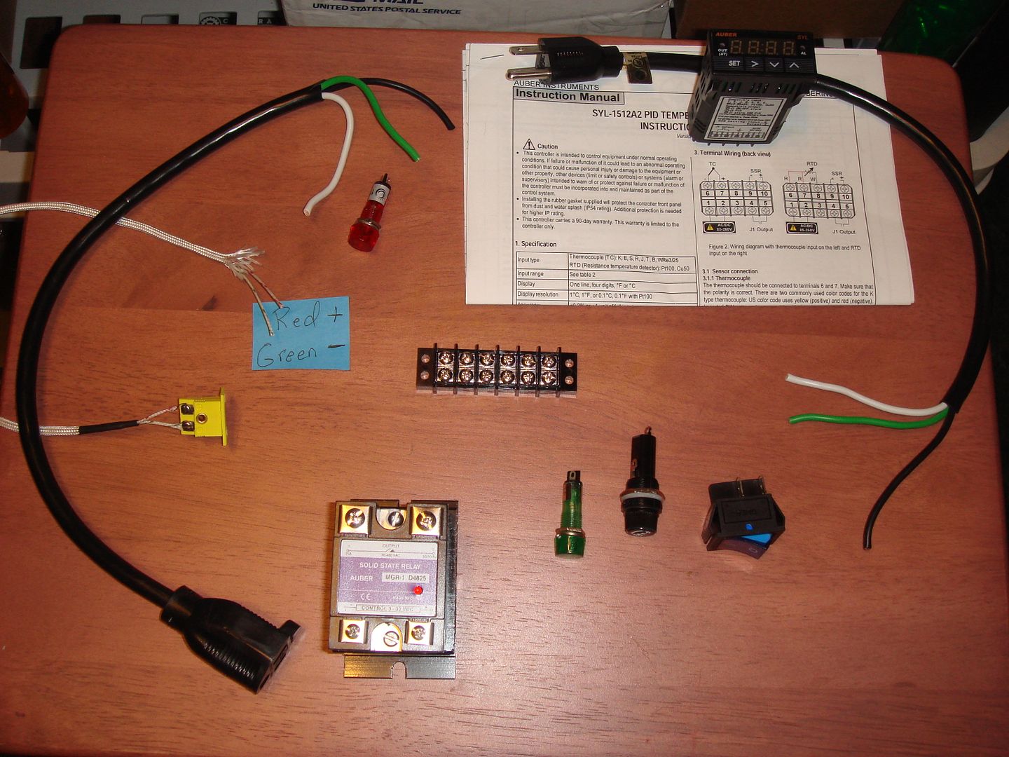
I got a lot of parts collected. Now just to figure out how to hook enough of em together to get a working PID. I'd like to have one for my lino pot.
I'm calling it the May PID project, because it'll probably take me all of May to get this thing together!  I believe I started collecting these parts sometime around last June and this is how far I've gotten. I believe I started collecting these parts sometime around last June and this is how far I've gotten. I'm a lost pup in the electrical world.  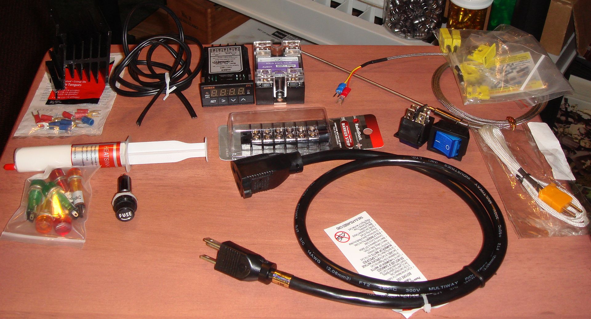
__________________
. . . Have a Colt and a smile.
|

|
|
April 27, 2014, 11:05 AM
|
#2 |
|
Senior Member
Join Date: April 8, 2000
Posts: 2,101
|
Just take the other one apart, then you'll know how to build the new one....
__________________
LAter, Mike / TX |
|
|
|
April 27, 2014, 11:37 AM
|
#3 |
|
Senior Member
Join Date: January 7, 2012
Location: Auburn, AL.
Posts: 2,332
|
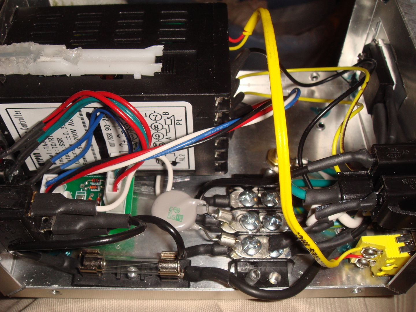
It has a circuit board and capacitor lookin' thingys and everthang is a different color and shape!
__________________
. . . Have a Colt and a smile.
Last edited by Beagle333; April 27, 2014 at 11:46 AM. |
|
|
|
April 28, 2014, 09:00 AM
|
#4 |
|
Senior Member
Join Date: April 8, 2000
Posts: 2,101
|
I see.....well I ca pull mine apart, but that necessarily make things much easier on ya, I did build it myself ya know..
Hope the worst of that weather wasn't over you guys last night. Saw it on the news this morning at 04:15 before I headed in to work. Looked pretty bad there for some...prayers sent for those.
__________________
LAter, Mike / TX |
|
|
|
April 28, 2014, 11:47 AM
|
#5 |
|
Senior Member
Join Date: May 20, 2001
Location: Oshkosh wi.
Posts: 3,055
|
I've never seen a capacitor or a resistor used in a pid circuit.
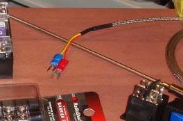
Another thing I see is a bigger wire used on the inside of the thermocouple (TC) plug. That wire HAS to be the same wire that the TC uses. I don't know much about electronics, but I think it has to do with impedance. The resistance of the wire is different, it causes an error in the TC's reading. I just cut off a chunk of the TC wire to use on the inside of the plug to the PID.
__________________
The more people I meet, the more I love my dog They're going to get their butts kicked over there this election. How come people can't spell and use words correctly? |
|
|
|
April 28, 2014, 12:45 PM
|
#6 |
|
Senior Member
Join Date: January 7, 2012
Location: Auburn, AL.
Posts: 2,332
|
It's all new to me.....
I'm not at home to compare..... Are you saying this red and yellow wire doesn't match the red and yellow wire inside the box?
__________________
. . . Have a Colt and a smile.
|
|
|
|
April 28, 2014, 01:04 PM
|
#7 | |
|
Senior Member
Join Date: May 20, 2001
Location: Oshkosh wi.
Posts: 3,055
|
Quote:
__________________
The more people I meet, the more I love my dog They're going to get their butts kicked over there this election. How come people can't spell and use words correctly? |
|
|
|
|
April 28, 2014, 01:07 PM
|
#8 |
|
Senior Member
Join Date: January 7, 2012
Location: Auburn, AL.
Posts: 2,332
|
Thanks for pointing that out... I will be sure to watch for that when I build mine and make sure they match. I hadn't thought about that.
 I still need to get some smaller wire (than that lamp cord) for the neon lamps and the AC power to the controller, and a 10A fuse for that fuseholder. 'Dunno why they didn't sell it with one! 
__________________
. . . Have a Colt and a smile.
|
|
|
|
April 28, 2014, 01:37 PM
|
#9 | |
|
Senior Member
Join Date: January 7, 2012
Location: Auburn, AL.
Posts: 2,332
|
Did a little research on it too, and the round gray thing isn't a capacitor, it's something called a MOV, which somehow filters voltage spikes.
Mine ain't gonna have one of them. Quote:
__________________
. . . Have a Colt and a smile.
|
|
|
|
|
April 28, 2014, 05:03 PM
|
#10 |
|
Senior Member
Join Date: April 8, 2000
Posts: 2,101
|
Well mine don't have those extra gidgets and seems to work just fine.
Iffin you want I can pull the screws outta my box and take a few shots for ya. Can't say it will be all professional looking like yours though, I didn't use all that shrink tube and all on my connections, might not have even used terminals..  Still works though for the pot and the lubesizer.... Still works though for the pot and the lubesizer....Stupid me, I took several pictures of the wiring and how it all goes. Needed to anyway as I have one sitting there in a similar condition to the one you have, that I need to put together myself. Pretty simple really, just hook the black wires together with a jumper running to the controller, then the white wires are used to run to the other terminal and through the relay and such, and yea the thermocouple wires go to the terminals on the top. See nothing to it. Anyway the camera was set to like infinity size pic's so I need to retake them at a size that will upload or resize the ones I already took. I'll get them up after I eat a bite. Here we go...
__________________
LAter, Mike / TX Last edited by Mike / Tx; April 28, 2014 at 07:37 PM. |
|
|
|
April 28, 2014, 05:47 PM
|
#11 |
|
Senior Member
Join Date: January 7, 2012
Location: Auburn, AL.
Posts: 2,332
|
Mine ain't gonna look professional. This was a demo photo of what it should look like. Mine is being built in a Medium Flat Rate box. Mostly 'cause nobody's done it before and secondly because I think it's funny.
 More pics would be helpful though! I had to ask somebody if I put the new end plug on my air compressor the right way after I burned it off the other day. So I'm not real 'lectrical talented.
__________________
. . . Have a Colt and a smile.
|
|
|
|
April 28, 2014, 08:14 PM
|
#12 |
|
Senior Member
Join Date: April 8, 2000
Posts: 2,101
|
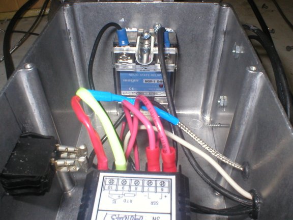
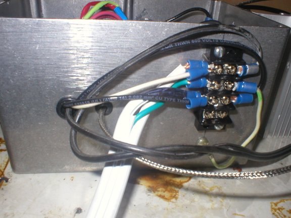
Ok if you see the white wires below. Moving from left to right in the top picture this post. One from each of the big cords are on the first terminal of the controller.
On the second terminal, there is the black from the male plug cord, and a white which goes out of the box and around to the top right terminal on the relay, which is shown in the bottom pic of the other post. ( I say top right. This is if your looking at it upright, if you follow me. Bottom Pic of top post.) The black wires which are nutted together, one is from the female plug cord, the other one goes out the box and around to the top left terminal on the relay, opposite the white. On the third terminal of the controller, is a black wire. It runs out of the box and attaches to the bottom left terminal of the relay. On the fourth terminal of the controller, is the red wire. It goes out of the box and attaches to the bottom right terminal on the relay. The RTD wires connect to the terminals #5 and 4 opposite side from the power wires. Ok about all those flashy lights and other stuff you have, well your on your own with those. As you see mine is pretty straight forward and simple. When the numbers are on, so is the power. I just like the KISS principle. Now if I can get this one all put back together, and wire up the other one tomorrow, I will be all set to pour AND lube....
__________________
LAter, Mike / TX |
|
|
|
April 28, 2014, 08:21 PM
|
#13 |
|
Senior Member
Join Date: January 7, 2012
Location: Auburn, AL.
Posts: 2,332
|
Ahhhh, that'll help some!Thanks Mike! I'll make sure my connections go to someplace similar. The lights are just tied in at various places and don't really affect the basic function, so it's about the same kind of setup.
I gotta get some smaller wire and a fuse and I'll be set to try putting all this mess together. 
__________________
. . . Have a Colt and a smile.
|
|
|
|
April 30, 2014, 05:37 PM
|
#14 |
|
Senior Member
Join Date: May 20, 2001
Location: Oshkosh wi.
Posts: 3,055
|
Here's mine;
  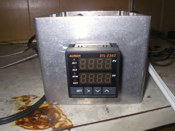 I'll try to find the wiring diagram I used, it was on the special projects forum on the cast boolits website. Without a wiring diagram, you could damage the PID. I used a auberin PID, it has different numbered terminals than most others.
__________________
The more people I meet, the more I love my dog They're going to get their butts kicked over there this election. How come people can't spell and use words correctly? |
|
|
|
April 30, 2014, 06:36 PM
|
#15 |
|
Senior Member
Join Date: January 7, 2012
Location: Auburn, AL.
Posts: 2,332
|
Thanks for those pics too!
Mine is an Auberin SYL1512A. I woulda got the dual display, but the guy who was advising me at the time, seemed to prefer the cheaper price over the model showing both set temp and actual temp at the same time.
I downloaded the manual so I would know what terminals go where. I'd sure hate to let the smoke out of it on my first attempt!
__________________
. . . Have a Colt and a smile.
|
|
|
|
June 1, 2014, 10:15 PM
|
#16 |
|
Senior Member
Join Date: January 7, 2012
Location: Auburn, AL.
Posts: 2,332
|
I'm making great progress in this, I think. I got it all layed out now.
 I just got busy and shelved it for a while.... now I'm revisiting it and am going to finish the photo journey of the build.
__________________
. . . Have a Colt and a smile.
Last edited by Beagle333; June 1, 2014 at 10:21 PM. |
|
|
|
June 4, 2014, 06:47 PM
|
#17 |
|
Senior Member
Join Date: January 7, 2012
Location: Auburn, AL.
Posts: 2,332
|
Slowly..... but, well... just slowly.
Alright...... I got it now..... stay tuned for pics. It's not terribly difficult, I just didn't want to burn up anything expensive while learning.
Here's the final cartoon drawing of the wiring, though. 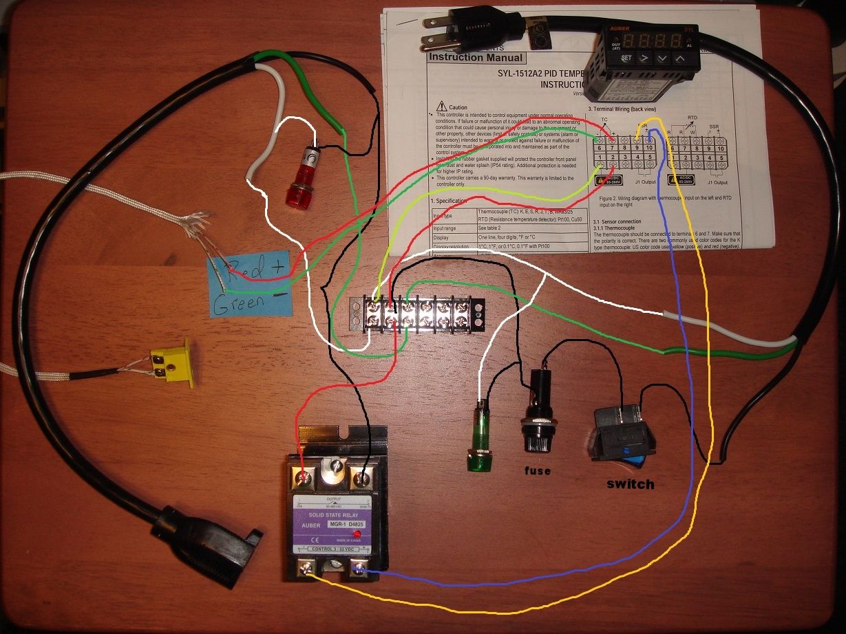
__________________
. . . Have a Colt and a smile.
Last edited by Beagle333; June 5, 2014 at 09:28 PM. Reason: 'cause it's Thursday |
|
|
|
June 8, 2014, 03:00 PM
|
#18 |
|
Senior Member
Join Date: January 7, 2012
Location: Auburn, AL.
Posts: 2,332
|
Well... here it is.
Proof positive that anybody can build one of these!I used a MFR box, because it was roomy, free, and unique! You can't really tell it, but all the cutouts were reinforced with a layer of "cut up milk jug" plastic and taped over before being cut. I thought the cardboard might get fatigued after some use without some sort of support around the things I'd be pushing and pulling on. Also the PID, power switch, and K-plug have clips that need to snap into a properly sized rigid opening to keep them in place. 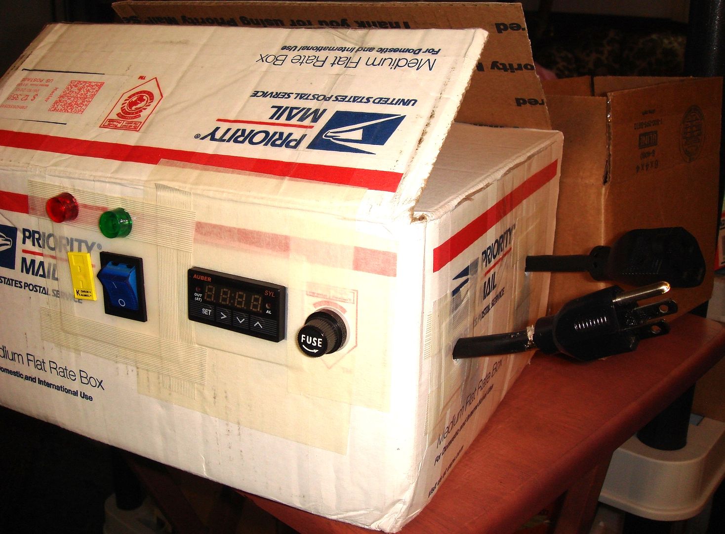 The innards, unsorted: 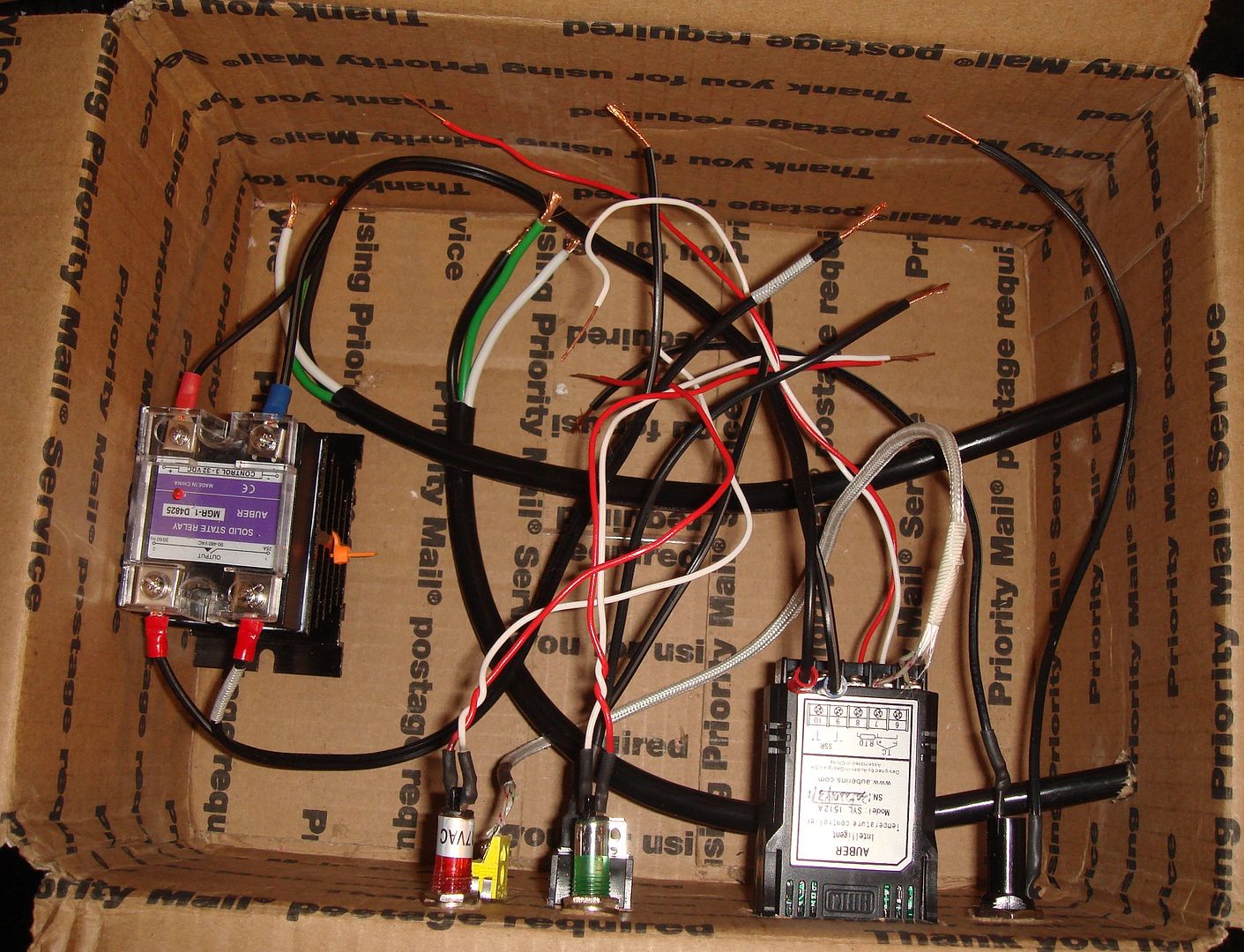 All wire-nutted up. I decided not to use the little terminal block. I'll use that in my next, smaller one. 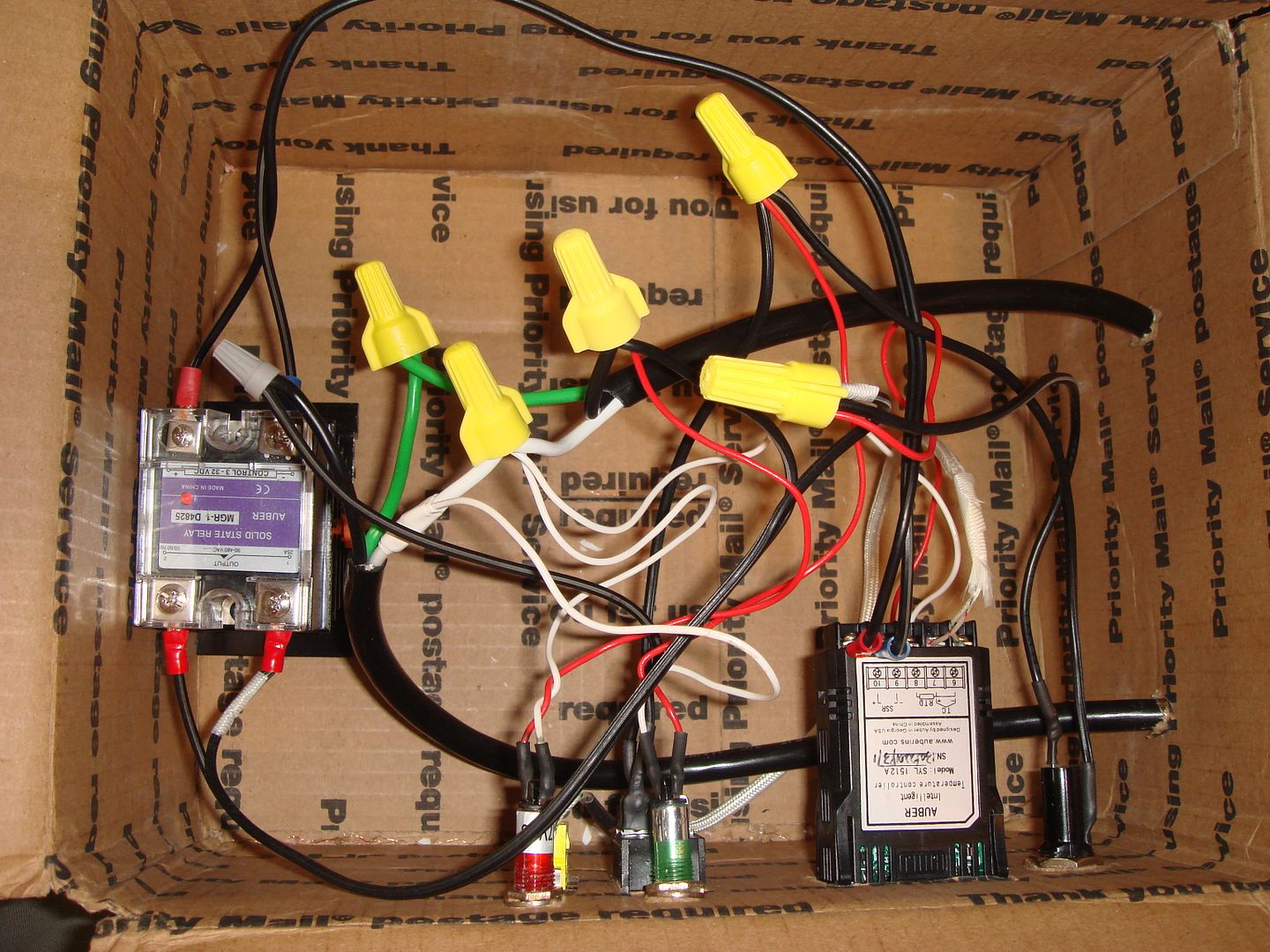 And.... it works! The green light tells me that the power is on, and the orange light tells me when it's sending power out. 'Both unneeded, but I had them and wanted to put them somewhere. 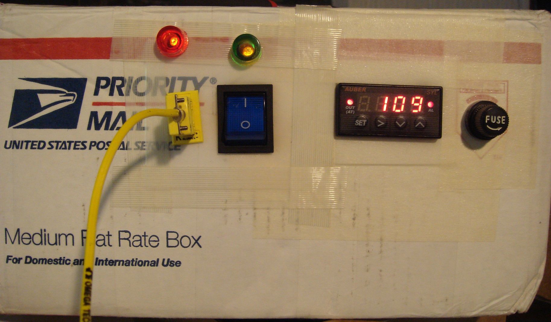 Thanks for the helpful comments!
__________________
. . . Have a Colt and a smile.
|
|
|
|
June 9, 2014, 03:16 PM
|
#19 |
|
Senior Member
Join Date: July 1, 2013
Location: Douglasville, Ga
Posts: 4,615
|
ok, so what does it do??
__________________
My head is bloody, but unbowed |
|
|
|
June 9, 2014, 05:19 PM
|
#20 |
|
Senior Member
Join Date: January 7, 2012
Location: Auburn, AL.
Posts: 2,332
|
It's just a fancy 'puterized thermostat that "learns" what it is controlling. I use it for my lubesizer heater, my lead pot and my powdercoating toaster oven.
It will regulate anything to within 2± degrees of the set temperature. That means no fluctuations of 50° or more with your lead pot while you are casting, or no over/under cooking of the powdercoat (or biscuits, if that's what you decide to bake ), or no fiddling around with the lube heater on the sizer (notorious for either leaving the lube hard and difficult to apply, or so warm that it drips out the bottom of the die.)It learns how fast whatever you are using heats up and how fast it reheats. Let's say you set a regular thermostat at 700°..... when your thermostat gets there, it clicks off, and your coils are still glowing red hot and your pot of lead ends up at 730°, then it begins cooling down and your thermostat lets it cool down to 680° before it kicks back on for a heat cycle. Your lead cools on down to 675° before the coils get red again and start transferring heat through the metal pot and the temp will climb back to 700°+ and the cycle will start all over again. This thing will "learn" (autotune) as to how much it takes to get your pot to exactly 700° and start "slowing down" or "coasting" before it gets there, sort of like you anticipate a stop sign and don't roar all the way up to it at 55mph. So it eases up to the set temp and then it knows how much to intermittently apply to keep it at 700° by using short bursts and pulses instead of getting the coils glowing again, so it adjusts it in tiny increments now and the lead (or oven or whatever) stays right at perfect temp. It will also learn how much it takes to keep it hot with whatever load you are heating, and so your pot won't get hotter and hotter as the lead level drops, like most pots will do. And if you add more lead to the pot or change the tray of bullets baking in the powdercoat, it won't just apply full power and overshoot, it'll hit it hard for a minute or so and then slow down as it approaches the target temp again.
__________________
. . . Have a Colt and a smile.
|
|
|
|
June 9, 2014, 05:33 PM
|
#21 |
|
Senior Member
Join Date: April 8, 2000
Posts: 2,101
|
OK you almost had to buy me a new keyboard, but thankfully the coffee this morning didn't ruin it, an the kkkkkeysssss only stttttttttttick onccce in a while... gotta luv it.... and to think I was wondering what to put mine in the other day, and have probably half a dozen of those boxes sitting around. Well I would have to empty the ingots out of them first, but hey, kill two birds with one rock I guess. Glad to see you got that thing going. Heck I haven't had time to run the one I already have built, much less worry about the new one yet.
__________________
LAter, Mike / TX |
|
|
|
June 9, 2014, 05:47 PM
|
#22 |
|
Senior Member
Join Date: January 7, 2012
Location: Auburn, AL.
Posts: 2,332
|
And this one only took me a year to build! I better start orderin' parts now!
Mebbe I can cut the build time down to 6 months on the second one!
__________________
. . . Have a Colt and a smile.
|
|
|
|
June 9, 2014, 08:21 PM
|
#23 |
|
Senior Member
Join Date: July 1, 2013
Location: Douglasville, Ga
Posts: 4,615
|
very cool, im not up to that level of precision yet, but i love your engenuity
__________________
My head is bloody, but unbowed |
|
|
|
June 9, 2014, 10:15 PM
|
#24 |
|
Senior Member
Join Date: January 16, 2011
Location: North Bend, OR
Posts: 743
|
It would never have occured to me to use a cardboard box. I constructed a box frame from 1"x1" wood stock and covered it with 1/8" plywood and then installed my pid in that.
|
|
|
 |
|
|


