
|
|
|||||||
| Forum Rules | Firearms Safety | Firearms Photos | Links | Library | Lost Password | Email Changes |
| Register | FAQ | Calendar | Today's Posts | Search |
 |
|
|
Thread Tools | Search this Thread |
 October 20, 2013, 02:54 PM
|
#1 |
|
Senior Member
Join Date: November 25, 2012
Location: Cascadia
Posts: 1,295
|
1911 grip screw locations
Does anyone know the measurement of the distance between the two grip screws of a full size 1911 center to center?
I decided just for fun to make my own wood grips. Seemed like a simple task but in reality there is some tight specs on the hole locations as well as fitting the grip holes to the grip screw bushings. Everything else was easy enough but you cant drill the mounting holes by eye even if you use an existing grip as a pattern. I came very close but 'might' have to start over depending on how well I machine the counterbore for the screw and if the screw provides enough grip on the wood. If I have to start over, I'd like to know the spacing between the two screw locations center to center and build a drill jig
__________________
lightweight, cheap, strong... pick 2 |

|
|
October 20, 2013, 03:40 PM
|
#2 |
|
Senior Member
Join Date: November 21, 2011
Location: Southern Louisiana
Posts: 1,399
|
3 1/16 seems to be a popular dimension. Hogue makes lots of 1911 grips and they seem pretty happy with it:
http://www.hoguestore.com/index.php?...&cPath=524_525 3 1/16 = 3.0625", frame drawing dimensions work out to 3.0600" between the holes. Unless you're using something like a mill to make your jig, you'll never see those 2.5 thousandths. 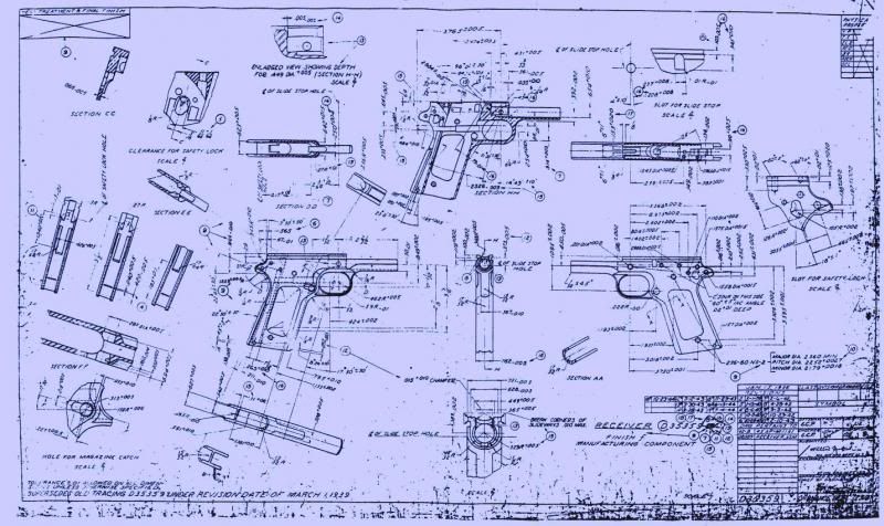
Last edited by 45_auto; October 20, 2013 at 03:53 PM. |
|
|
|
October 20, 2013, 05:18 PM
|
#3 |
|
Senior Member
Join Date: October 24, 2008
Location: Naples, Fl
Posts: 5,440
|
Koda
I am getting ready to do the same thing but this pistol is a Ballester Molina. The location of the screw holes in this pistol is a little off in comparison with the location of the ones in a spec 1911.
I am going to mark the location by holding one grip in place and then going through the screw holes in the frame with a scribe or sumpin.
__________________
Seek truth. Relax. Take a breath. |
|
|
|
October 20, 2013, 05:21 PM
|
#4 | |
|
Senior Member
Join Date: November 25, 2012
Location: Cascadia
Posts: 1,295
|
Quote:
I did google it but my google-fu was not so strong.... seems like a simple thing. I also didn't think to google actual CAD drawings which as a draftsman I can appreciate. Take a look at this link for some nice and clear detailed drawings: http://www.m1911.org/M1911-A1_REDUX.pdf only .014" different than the 3 1/16 houge references, no big deal. It looks like the origin of the grip bushings is from the slide stop hole which makes the hole to hole a reference I can do the math later if I get bored to see it exact.
__________________
lightweight, cheap, strong... pick 2 |
|
|
|
|
October 20, 2013, 05:41 PM
|
#5 | |
|
Senior Member
Join Date: November 25, 2012
Location: Cascadia
Posts: 1,295
|
Quote:
Doc, I used an existing grip to mark the hole locations and then used a drill press with a pilot hole drilled first located by eye. I used calipers to measure what drill diameter to fit to the bushing... in the end by eye the positioning was not exact but my drill diameter was a tight fit so I reamed out one of the holes in the direction it needed and it fit but then this slightly threw off the grip geometry (shape) and I had to retouch up which I forgot about. So if you try this start with drilling the holes first, check the fit and if it works continue on with the rest of the shaping. Will save much time. Also, the thickness of the grip is critical too and must be exact to fit the height of the grip screw installed in the bushing. If I have to ream any more then I think the grips will be too loose on the frame. I did buy an end mill to make the counterbores for the screw heads which hasn't come in yet.
__________________
lightweight, cheap, strong... pick 2 |
|
|
|
|
October 21, 2013, 09:24 AM
|
#6 |
|
Senior Member
Join Date: September 28, 2008
Posts: 10,442
|
Doc sez "I am going to mark the location by holding one grip in place and then going through the screw holes in the frame with a scribe or sumpin."
That's the way I would do it, too. But make sure whatever tool is being used to make the mark is a tight fit in the frame holes, or it will wobble and throw things off.
__________________
Walt Kelly, alias Pogo, sez: “Don't take life so serious, son, it ain't nohow permanent.” |
|
|
|
October 21, 2013, 09:44 AM
|
#7 |
|
Senior Member
Join Date: October 24, 2008
Location: Naples, Fl
Posts: 5,440
|
BTW Koda....
....I like the progress you are making on the grips.
I think they are going to look real sweet!
__________________
Seek truth. Relax. Take a breath. |
|
|
|
October 22, 2013, 02:24 AM
|
#8 | |
|
Senior Member
Join Date: November 25, 2012
Location: Cascadia
Posts: 1,295
|
Quote:
I finished my first set tonight and considering these "prototypes", they look ok and are functional but flawed cause I screwed up placing one of the cbores... I can do better but these helped me identify all the pitfalls. Here is the lowdown... >It is possible to drill and cbore the mounting holes by eye but really not the way to go. I don't have a mill and cant brainstorm a home made drill press fixture right now but am thinking a cross slide drill press vise might work. Problem is the hole pattern is not parallel with either of the straight sides of the grips and unless you want to completely strip your frame you have to shape the grip profile first which is too much work invested if you screw up the hole to hole location. I think the trick to doing this by eye is to mark the holes with an original grip but do not unclamp the grip from drillpress after drilling and switch over to the endmill to do the screwhead side cbore. Repeat this for each of the 4 holes. There is a cbore needed on the frame side but not as critical and will never show if you err and fix you'd have to unclamp the grips anyways. >As I mentioned earlier its important to match the grip height to the bushing and screw head assembly height. I want my screw heads below flush in the cbore. In the second photo I shaped the outside profile with a coarse file by hand, this was easy enough to do... I went too far. I checked on Google and found low profile/slim grip screws and bushings from edbrown.com affordable so I ordered some they came in just a couple days, faster than the end mill from McMaster. >Colt stakes their grip bushings. It was kind of a commitment when deciding to remove them cause you cant re-use them. FWIW, edbrown.com sells very nice cocobolo wood grips in regular and slim profile for only ~40 bucks... >last pitfall is my new rotary tool from Harbor Freight broke when milling out the relief area for the safety plunger tube. Everytime I buy cheap tooling I get a reminder why I shouldn't. So next up I want to make a new set over again. I'm thinking of using the prototypes to see if I can hand make a large diamond shape in the center with checkering IDK. Either way ideally I want to sand the grips smooth and lacquer them. I need to get some locktite for the new bushings.
__________________
lightweight, cheap, strong... pick 2 |
|
|
|
|
October 22, 2013, 02:38 AM
|
#9 | |
|
Senior Member
Join Date: November 25, 2012
Location: Cascadia
Posts: 1,295
|
Quote:
__________________
lightweight, cheap, strong... pick 2 |
|
|
|
|
October 22, 2013, 03:42 AM
|
#10 |
|
Senior Member
Join Date: November 13, 2006
Posts: 8,288
|
I have access to a Bridgeport.That spoils me a bit.Creativity and a drill press will take you pretty far.
I might drill my holes in the slabs first.then shape the grips. If you put the slabs in a drill press vise,or any square,straight workholding device,you can slide it on a fence clamped to the table,so the spindle is centered on the centerline of the grip slabs. Now,set a stop(C clamp?) for either your workpiece or vise to stop against. Datum 1 is the table,datum 2 is the fence,datum 3 is the stop.Precise location.Now you need a spacer,anything 3.062,(and,it can be stacked,like gage blocks),to place between the stop and your vise or workpiece,to move it 3.062. On a mill,I center workpieces and holes,line things up,and "tram" the mill head square to the table with a dial test indicator...but,if you do not have one,you would be amazedhow close you can set up just putting a bent piece of wire in the chuck and using it to center a workpiece,etc. Bend the wire and rotate the chuck to find one edge,rotate the chuck 180 deg,look at the gap.Move the workpiece half way.Do it again.With patience,a good eye,and/or a loupe,you can work to .002 or .003,easy.Its like using open sights.Same gap each side. Keep having fun! Oh,look in the online tool catalogue like MSC or Enco at "transfer punches" and "transfer screws".See if those give you ideas.I doubt you can buy any just exactly right,but they might give you an idea. If you want to make yourself crazy,go on ebay and search "ironwood slabs "or"stag horn slabs" etc...one thing will lead to another! Last edited by HiBC; October 22, 2013 at 03:52 AM. |
|
|
|
October 22, 2013, 04:45 AM
|
#11 |
|
Senior Member
Join Date: October 24, 2008
Location: Naples, Fl
Posts: 5,440
|
Here is an idea...
Get a piece of 3/4 plywood that can be placed on top of the drill press table. Don't clamp it to the table, just let it float. Maybe ten inches by ten inches.
You should be able to accurately locate the screw holes in the grips. Mark them and clamp them to the plywood cover over the table. A coupla pieces of plywood that are one inch by four inches each of which is drilled with a quarter inch hole should work. Use a 3/16th inch screw through the small block and into the larger plywood base. Place one end of the small block on the grip and the other end rests on the plywood base. Tighten the 3/16th screw until the grip is held snug but not tight enough to bruise the surface. Two such hold down clamps on one grip should hold it in place. Drill one screw hole and then without moving the base, replace the bit you used for the screw hole with the one you will use for the cbore. Hint: A set of Forstner bits from Horrible Freight is about thirty bucks. They work well as counter bores for wood. Repeat the operation for the other hole then repeat the whole operation for the other grip.
__________________
Seek truth. Relax. Take a breath. |
|
|
|
October 22, 2013, 04:50 AM
|
#12 |
|
Senior Member
Join Date: October 24, 2008
Location: Naples, Fl
Posts: 5,440
|
Here is another thought...
On the grips I have on the Ballester Molina, the depth of the counter bore is critical in its precision.
Too shallow and you don't catch all of the threads making it more likely that the frame holes will strip. Too deep and the grip screw interferes with the magazine. I would think this would be true of any 1911. I just came up with this Ballester Molina and the first thing I had to do was retap one of the frame holes and make a new screw for the grip.
__________________
Seek truth. Relax. Take a breath. |
|
|
|
October 22, 2013, 05:59 PM
|
#13 |
|
Senior Member
Join Date: October 24, 2008
Location: Naples, Fl
Posts: 5,440
|
PIcture worth a thousand words
This is what I meant.
  Clamps hold the base in one spot. and the wooden hold downs hold the grips in one spot. Then it is just a matter of drilling and counterboring each hole one at a time. Change only the bit and the workpiece stays put. I used a real small bit for a pilot hole. Easier to locate the smaller hole, then move up to the right bit for the shank hole. Made a counterbore bit from an old broken drill bit.
__________________
Seek truth. Relax. Take a breath. |
|
|
|
October 22, 2013, 09:31 PM
|
#14 | ||||
|
Senior Member
Join Date: November 25, 2012
Location: Cascadia
Posts: 1,295
|
Quote:
Quote:
Quote:
Quote:
Fun conversation all, its a fun after work project I'll post photos of my next set completed (it could be a few days though).
__________________
lightweight, cheap, strong... pick 2 |
||||
|
|
|
October 23, 2013, 06:28 AM
|
#15 |
|
Senior Member
Join Date: October 24, 2008
Location: Naples, Fl
Posts: 5,440
|
Koda....
You are correct....
On my BM there are no bushings. Screws straight into the metal of the frame. I tried the base and clamps with my own yesterday and was able to get them pretty close. Images are on the Curios and Relics forum. Yesterday I recommended the Forstner bits from Harbor Freight but I found that the bits in the set are nowhere close to the size that the counter bore needs to be. I had to make a counterbore bit from a broken drill bit.
__________________
Seek truth. Relax. Take a breath. |
|
|
|
November 20, 2013, 01:20 AM
|
#16 |
|
Senior Member
Join Date: November 25, 2012
Location: Cascadia
Posts: 1,295
|
Just wanted to follow up with this, after a few weeks hiatus I finished my project. I used some of the input from HiBC and Doc Hoy much obliged.
The journey was long and painful for a garage project but I prevailed. I made a fence and block to drill the holes, and clamped the workpiece later per Doc Hoy's advice after centering the drill per HiBC's advice. This isnt CNC precision mind you but in the end precise enough to barely discern by eye. I can now take pride in making my own grips that dropped right onto the pistol perfectly. The hardest part of this project is positioning the thru holes 3.074" apart and centering the cbores over them and not drilling the cbores too deep. I love the look and feel of the slim grips. For this set I switched to oak material with a light "Sedona Red" stain and seal for my full size govt...
__________________
lightweight, cheap, strong... pick 2 |
|
|
|
November 20, 2013, 01:23 AM
|
#17 |
|
Senior Member
Join Date: November 25, 2012
Location: Cascadia
Posts: 1,295
|
installed
__________________
lightweight, cheap, strong... pick 2 |
|
|
|
November 20, 2013, 01:12 PM
|
#18 |
|
Senior Member
Join Date: July 27, 2009
Location: Ft. Polk
Posts: 883
|
Looks really nice.
__________________
Freedom's just a word. If I'm gonna die for a word, my word is jello... |
|
|
|
November 20, 2013, 03:47 PM
|
#19 |
|
Member In Memoriam
Join Date: March 17, 1999
Posts: 24,383
|
FWIW, you want to cut the hole so the screws will just touch the wood when they tighten up against the bushing. If you fit them so the screw heads crush the wood, the grips will loosen up.
Jim |
|
|
|
November 20, 2013, 09:55 PM
|
#20 | |
|
Senior Member
Join Date: November 25, 2012
Location: Cascadia
Posts: 1,295
|
Quote:
So simple on the surface it lured me in, but in reality this is not an easy task. If my grips loosen up I'll buy some new ones to replace. It was a fun couple evenings in the garage after work though...
__________________
lightweight, cheap, strong... pick 2 |
|
|
|
|
November 21, 2013, 12:38 AM
|
#21 |
|
Senior Member
Join Date: July 27, 2009
Location: Ft. Polk
Posts: 883
|
You mean you're gonna try again mo' betta this time and send me those faulty ones, right?

__________________
Freedom's just a word. If I'm gonna die for a word, my word is jello... |
|
|
|
November 23, 2013, 01:37 PM
|
#22 |
|
Staff
Join Date: March 4, 2005
Location: Ohio
Posts: 21,063
|
Koda94,
I downloaded the same file of old blueprints as 45 Auto did (zip file at m1911.org). As I read the drawing, with the slide rails horizontal, the vertical space between the frame screws is 2.878" and the horizontal offset is 1.081". The square root of the sum of the squares of those two numbers gives 3.0743", same as the modernized drawing file showed, so I think that's the right number. It's closest to 3 5/64", with is within 1.1 thousandths. The cumulative tolerance would be about ±4 thousandths. The error of 0.014 is almost a 64th, and is enough to make you widen a hole, so I would try to use the 3.074" setting on your calipers to scribe it.
__________________
Gunsite Orange Hat Family Member CMP Certified GSM Master Instructor NRA Certified Rifle Instructor NRA Benefactor Member and Golden Eagle |
|
|
|
|
|


