
|
|
|||||||
| Forum Rules | Firearms Safety | Firearms Photos | Links | Library | Lost Password | Email Changes |
| Register | FAQ | Calendar | Today's Posts | Search |
 |
|
|
Thread Tools | Search this Thread |
 December 12, 2017, 10:14 PM
|
#1 |
|
Junior Member
Join Date: December 11, 2017
Posts: 3
|
Calling all electrical experts induction help
I have dyi induction annealer that I constructed using a 1000watt induction board off amazon work with 12-48 v lots dc currently using a 12.7 825 watt power supply I have replaced the coil with #8 solid copper wire and made the diameter approx 1” inside. The issues I’m having is it will bring a drill bit 1/4” to 1200 degrees in 18 sec but I’m unable to reach the 725-750 degree mark on a piece of 6.5 hornady brass it gets to approx 380 using a thermal camera. This is in a 2 min time. What are some suggestions or fixes that I could try. Thanks in advance
|

|
|
December 12, 2017, 10:29 PM
|
#2 |
|
Staff
Join Date: February 12, 2001
Location: DFW Area
Posts: 24,990
|
Induction heating works better on ferrous metals than on non-ferrous metals and better on poorer conductors than on good conductors.
__________________
Do you know about the TEXAS State Rifle Association?
|
|
|
|
December 12, 2017, 10:50 PM
|
#3 |
|
Junior Member
Join Date: December 11, 2017
Posts: 3
|
I understand that induction works on an substance that is more ferrous but 1000s of piecesof brass are inductioned annealed everyday so it is possible. So I’m asking those that have constructed these diy’s for input on how to fix what I have
|
|
|
|
December 12, 2017, 11:21 PM
|
#4 |
|
Staff
Join Date: February 12, 2001
Location: DFW Area
Posts: 24,990
|
I have not built such a device, but the solution would appear to be "more power". I found one induction brass heater designed for your application and it was running at 1200 watts; about 50% more power than the spec for the power supply you're using.
__________________
Do you know about the TEXAS State Rifle Association?
|
|
|
|
December 12, 2017, 11:37 PM
|
#5 |
|
Senior Member
Join Date: September 28, 2013
Posts: 3,825
|
Try reducing the coil's diameter and increasing the number of turns.
-TL Sent from my SM-G930T using Tapatalk |
|
|
|
December 13, 2017, 01:07 AM
|
#6 |
|
Junior Member
Join Date: December 11, 2017
Posts: 3
|
Thank you I’m pretty close to the min diam but I will start playing with coil numbers I’m at 5 right now
|
|
|
|
December 13, 2017, 05:56 AM
|
#7 |
|
Senior Member
Join Date: December 22, 2015
Posts: 887
|
I'm not very familiar with induction heaters, but I believe the one you have won't produce rated power at 12V. You may need to increase the input voltage to 24V or more to get the power (heat) you need.
Last edited by BBarn; December 13, 2017 at 06:00 AM. Reason: Voltage typo |
|
|
|
December 13, 2017, 12:58 PM
|
#8 |
|
Senior Member
Join Date: April 25, 2008
Location: DFW area, Texas
Posts: 494
|
You might try using a 12 volt car battery as a power supply. That will give you all the amps you need. If that works, you need a bigger ac power supply. If it does not, you need more voltage such as a 24 volt supply rated at 1200 watts or so. Just be sure that you use big wire to connect with the auto battery.
Edit: The above assumes that your 1000 watt induction board will actually put out that power; made in China you never know. Also I'm assuming you have verified that 1000 watts is adequate for an induction anneal machine since I have no direct experience with them. Edit #2: Here's an off the wall suggestion since you are experimenting. Maybe your induction coil would benefit by using Litz wire https://en.wikipedia.org/wiki/Litz_wire. Note that it is used in induction heating to alleviate the "skin effect" of normal wire at low frequencies. Read the first paragraph in the "How Litz wire works" section and note the tubing reference. Since the wire is hard to find and fairly expensive and also a PIA to strip, I'd go to Home Depot or Lowes and buy a foot of 1/8 inch copper tubing and wind the coil out of that. Have no idea if that would work (I still suspect you need more voltage/power), but it would be a cheap and fun experiment. Last edited by mkl; December 14, 2017 at 01:52 PM. Reason: Added the "Edit" paragraph |
|
|
|
December 14, 2017, 11:15 PM
|
#9 |
|
Senior Member
Join Date: April 10, 2008
Location: Alaska
Posts: 7,014
|
Maybe Jeephamer will weight in, but 1 inch diameter?
The coils needs to be fairly close fitting, not tight, but more like 1/2 diameter. It also depends on if the power is stepped down to a nominal voltage (12) or you are only getting 250 Watts. My Annie is 1200 watts so power if you are getting it is in the ballpark. But coil closeness, turns and the wire type all play a factor in this. I work a lot of electronics but designing is not my forte, I fix em, the theory gets too far out for me.
__________________
Science and Facts are True whether you believe it or not |
|
|
|
December 15, 2017, 05:19 PM
|
#10 |
|
Senior Member
Join Date: June 8, 2016
Location: Cleveland, Ohio Suburbs
Posts: 1,750
|
You likely have a SainSmart 1000W ZVS Low voltage induction heating board module/Tesla coil 12V-48V or similar from Amazon. I will tell you what your problem likely is. You are driving the board with a 12.7 Volt 825 Watt power supply or roughly a 12 volt supply capable of delivering about 65 Amps.
The problem is in how these boards actually work. The board is capable of about 1 KW but you will only get that with the maximum DC Voltage of 48 VDC applied. With 48 VDC applied the board will draw right around 20.8 Amps of current so we get 20.8 Amps * 48 Volts = 998.4 or roughly 1,000 Watts (1.0 KW). With 12 VDC applied that board will only draw about 5 Amps or roughly 1/4 the current it would draw at 48 Volts applied. The fact that your power supply can supply more current at 12 Volts really matters not. Your actual power with your configuration is about 250 Watts. Connecting the unit to a car battery won't make any difference. While your existing 12 VDC supply is capable of about 825 / 12.7 = 64.9 Amps the induction heater board will only draw about 5 Amps with 12 Volts applied. I do not recommend changing the coil and the reasoning is that the unit was designed to operate at a given frequency with a coil having the Inductance it shipped with. You can get by with minor changes but I seriously doubt you will get the results you want making changes to the coil. The little black gizmo parts mounted to the aluminum heat sinks are MOSFET devices and if you start changing things they won't oscillate and there is a possibility they will become suicidal (bad things happen). Your best bet is increase the Voltage and as mentioned when doing so make sure you use wire which will handle the current. Going to a 24 Volt supply that board will draw about 10 Amps and allowing a margin I would use AWG 14 wire. Ron |
|
|
|
December 16, 2017, 02:20 PM
|
#11 |
|
Senior Member
Join Date: April 10, 2008
Location: Alaska
Posts: 7,014
|
Sweet. I can track that, sure don't know it in that depth.
__________________
Science and Facts are True whether you believe it or not |
|
|
|
December 16, 2017, 02:39 PM
|
#12 | |
|
Staff
Join Date: March 4, 2005
Location: Ohio
Posts: 21,063
|
Quote:
__________________
Gunsite Orange Hat Family Member CMP Certified GSM Master Instructor NRA Certified Rifle Instructor NRA Benefactor Member and Golden Eagle |
|
|
|
|
December 16, 2017, 03:01 PM
|
#13 |
|
Senior Member
Join Date: April 10, 2008
Location: Alaska
Posts: 7,014
|
I am going to disagree Formula is E x I = P
 If you double the voltage the power goes up to 120 Watts (24 x 5) Power consumed is not necessarily power delivered but the voltage current relationship is linear.
__________________
Science and Facts are True whether you believe it or not Last edited by RC20; December 16, 2017 at 04:23 PM. |
|
|
|
December 16, 2017, 03:04 PM
|
#14 | |
|
Senior Member
Join Date: April 10, 2008
Location: Alaska
Posts: 7,014
|
I ran the numbers, it would take 21 amps with 48 volts (rounded) to get 1000 watts out of that power supply and that assumes it goes to the coil with no loses (can't happen)
That is matches Reloadron input (pun) However, he needs 40 amps at 24 to get the 1000 - otherwise at 10 amps he gets at most 240. Quote:
__________________
Science and Facts are True whether you believe it or not |
|
|
|
|
December 16, 2017, 03:49 PM
|
#15 | |
|
Staff
Join Date: March 4, 2005
Location: Ohio
Posts: 21,063
|
Quote:
Ohm's law: E = IR To double E, you obviously have to at least double either I or R or use a combination of increases in the two that doubles E. The R will go up a bit as the brass heats further, but it won't heat further if the current moving in it remains the same. So raising the voltage will raise the current. If the load resistance remains constant, the current will double, so you will go from 12V×5A to 24V×10A. Power will then go from 60W to 240W, or an increase of a factor of 4. Since we changed the voltage times 2 and 4 is the square of two, the power has gone up as the square of the increase in voltage. P = EI = E²/R The above is true because, by Ohm's law, I = E/R and if you substitute that for I in the first form of the equation, you get EE/R or E²/R. In reality, the load resistance will not constant with heat, and you'd need a differential equation to find where the voltage and current actually reach equilibrium, but it will be at more than double the power. The real complication is we don't know how much power is lost in the coil resistance nor how much of the current is through reactive impedance instead of resistance. The actual power dissipated (or delivered) by an alternating current, unless you have a perfectly resistive load, is always complicated by the fact reactance (AC impedance due to inductance or capacitance) doesn't dissipate power; it merely goes into storing energy or comes from taking it back out of storage again. Since reactive current and resistive current are 90° out of phase with one another, the power dissipated by AC is: P = EI cos(Φ) Where Φ (phi) is the resultant phase angle from the combination of resistive and reactive currents. We don't really have a handle on that in these induction heaters without making some measurements, so we can't easily guess how much power is actually delivered to the case. We just know what the heaters claim to be capable of delivering to an ideal load.
__________________
Gunsite Orange Hat Family Member CMP Certified GSM Master Instructor NRA Certified Rifle Instructor NRA Benefactor Member and Golden Eagle |
|
|
|
|
December 16, 2017, 04:06 PM
|
#16 |
|
Senior Member
Join Date: April 10, 2008
Location: Alaska
Posts: 7,014
|
Unclenick:
That is where this all get tricky. Think of it as a fuel line. Assume the pressure is 12 psi and the line is partially blocked. Fuel flow is 5 gallon (minute). You only get 60 hp. Make it 24 psi and you double it to 10 gpm, you get 240 hp (still too little for your supersonic car but better) In other words its a dance. If you want to do 1000 mph, you need the power. If you have a board that can work from 12 to 48 volts, it has to have the 48 volts to move the amps to do the 1000 watt work. Now, its not always that simple in a electrical circuit, lots of factors can play in. You can't make more watts than the power allows. The board is starved for potential. Yes it could do 1000 watts with 12 volts, it needs to move 83 amps to do that. Heavier wires, components etc. More better to do it with 48 volts and 21 amps. Its all a dance.
__________________
Science and Facts are True whether you believe it or not |
|
|
|
December 16, 2017, 04:25 PM
|
#17 | |
|
Staff
Join Date: March 4, 2005
Location: Ohio
Posts: 21,063
|
Quote:
As to what limits the input current at the lower voltage, that's mainly going to be the coupling coefficient between the tank circuit coil and the load. Reducing the power feed resistance or the coil resistance or even going to bigger MOSFETs with lower RDS(ON) ratings, probably won't do much. I've been an electrical engineer and circuit designer since the mid-1970's, so if I have any of this wrong, I am in far deeper doo-doo than a mistaken Internet post amounts to.
__________________
Gunsite Orange Hat Family Member CMP Certified GSM Master Instructor NRA Certified Rifle Instructor NRA Benefactor Member and Golden Eagle |
|
|
|
|
December 16, 2017, 05:24 PM
|
#18 |
|
Senior Member
Join Date: April 10, 2008
Location: Alaska
Posts: 7,014
|
You are saying square and I am saying its linear darn it!
12 volts at 10 amps = 120 watts 24 volts at 10 amps = 240 watts. double voltage does not square the power if it was capable of changing the amps (power supply can do that if its setup to work that way - it just has to be robust enough. 12 x 10 = 120 12 x 20 + 240. A way to do that is variant resistance, lot of waste head though, brute forced thing best left for small drops. That is a square function but lots better ways do it.
__________________
Science and Facts are True whether you believe it or not |
|
|
|
December 16, 2017, 05:44 PM
|
#19 |
|
Junior Member
Join Date: November 15, 2017
Posts: 3
|
I believe he is saying it squares because for a given load, an increase in voltage will also increase current. I=V/R
|
|
|
|
December 16, 2017, 06:17 PM
|
#20 |
|
Staff
Join Date: March 4, 2005
Location: Ohio
Posts: 21,063
|
Yep. Exactly. You can't increase the voltage without increasing the current into machine. If the power supply is a current limiting type with a 5A limit, you could set it to 24V, but as soon as you powered the unit up, it would drop its output voltage back down to 12V, because that is what it would have to do to keep the current limited to 5A. You can't have both higher voltage and the same current unless the load itself is a constant current drain, and these very simple, inexpensive induction heater circuits are not such circuits.
P=EI Ohm's Law in its three forms: E=IR I=E/R R=E/I Suppose you have regulated power whose current limit exceeds anything drawn in this example: You apply 1V to a resistance 1Ω. Ohm's Law in the second form above says: I = E/R = 1V/1Ω = 1A Power dissipated in the load is then: P = EI = 1V×1A = 1W You apply 2V to the same load, a resistance of 1Ω. I = E/R = 2V/1Ω = 2A Power dissipated in the load is then: P = EI = 2V×2A = 4W You apply 3V to the same load, a resistance of 1Ω: I = E/R = 3V/1Ω = 3A Power dissipated in the load is then: P = EI = 3V×3A = 9W. So, as you increase voltage while keeping the load at a fixed resistance, the power goes up as the square of the change in voltage. That is not linear because power is the product of two factors that are going up at the same time, the same as a square is. Change in power would only be linear if you could increase the resistance in the circuit in proportion to the change in voltage, making one factor that increases power go up while another that decreases power goes up at the same time. For example: Suppose we go through the same numbers, but with resistance increasing with voltage. You apply 1V to a resistance 1Ω. Ohm's Law in the second form above says: I = E/R = 1V/1Ω = 1A Power dissipated in the load is then: P = EI = 1V×1A = 1W You apply 2V to a resistance of 2Ω. I = E/R = 2V/2Ω = 1A Power dissipated in the load is then: P = EI = 2V×1A = 2W You apply 3V to a resistance of 3Ω: I = E/R = 3V/3Ω = 1A Power dissipated in the load is then: P = EI = 3V×1A = 3W. You can see we had to increase the resistance of the load to hold the current down to its original value of 1A in order for power to go up directly (a linearl form) with voltage. But there in nothing in an induction heater load to make the resistance go up like that. When the resistance does not go up, use the second form of the power equation to avoid confusion: P = E²/R Again, this just substitutes the right side of the second form of Ohm's Law for I in the other form: P = E×I = E×E/R = E²/R
__________________
Gunsite Orange Hat Family Member CMP Certified GSM Master Instructor NRA Certified Rifle Instructor NRA Benefactor Member and Golden Eagle |
|
|
|
December 16, 2017, 08:05 PM
|
#21 |
|
Senior Member
Join Date: April 10, 2008
Location: Alaska
Posts: 7,014
|
I don't get into electrical discussions too often.
Frankly I think we have to disagree on this, you are introducing an element of resistance in this that does not factor in. Putting it simply, I double the voltage, the power only goes up double, not squared. Once the power supply has hit 100%, it can't pedal any faster. Resistance is not the varying element. I can take a VFD, aka Inverter aka UPS and vary the output voltage all I want within the limits of the voltage I have available. I can run a 480 volt 3 phase motor down to 100 volts with matching current, but I need the 480 if I want to run it up anywhere above 208 3 phase voltage. I can run a 480 volt motor on 208 3 phase (seldom see 240, only in a house) but I can't run it at its full current capability. And it better be VFD rated windings. In this case the circuit is simply starved for voltage to move the current through the board. You could build a device that could do it on 12 volts, but it would pull 63 amps. That means a whole lot heavier duty device., larger, more expensive. That same device could trim off up to any voltage you want, but it would be an expensive device for no gain. Far lower cost is to max the voltage and accept reduced output if you don't have that voltage (48 being chosen in this case as its a common DC output) You can adjust Ohms Laws (more accurately the power wheel) with resistance, but that is not what we are dealing with, whatever resistance is in that power supply is fixed. And that does not tell the real story, it may be running on IBGTs, it may be MOSFETs, It might be SCRs. If you want the full output you need more voltage. I can run the whole system at 208 3 phase, but then I need a step up transformer (or deal with a lot more current at the 208 level) the only circuit that the formula actually works on is a purely resistive DC circuit. In this case its a mess of diodes, tricacs resisters, transistors and some form of SCRs, MOSFETs, IBGTs (and capacitors). I had a guy take an electrical class and then tell me something smelled because he tried to apply it to AC Sorry bud, that's a whole different ball game. Its not that you can't calculate a DC circuit with the formula, you can only do it in discreet paths, what the whole adds up to is better left to computers.
__________________
Science and Facts are True whether you believe it or not |
|
|
|
December 16, 2017, 09:07 PM
|
#22 |
|
Senior Member
Join Date: December 22, 2015
Posts: 887
|
Its nearly certain that Unclenick is correct. The only way doubling the voltage won't quadruple the power is if the circuit under consideration has a constant current regulator on the front end (highly unlikely).
The schematics I've seen of these circuits are fairly simple and will draw proportionally more current as the voltage is increased (double the voltage and the current draw will also double). Therefore 2X the voltage and 2X the current equals 4X the power. BTW, if you actually have a power source with enough oomph to run that annealer at 1000 watts, you better have a fan blowing on those transistor heatsinks. Otherwise more than your brass will be annealed. |
|
|
|
December 16, 2017, 09:20 PM
|
#23 |
|
Senior Member
Join Date: June 8, 2016
Location: Cleveland, Ohio Suburbs
Posts: 1,750
|
<OffTopic>
This is in fact a gun forum correct? Fond memories of EL101 and as a rough guess in Nick's class give or take a few years.  Here is something I saw humorous and had to share. Before I retired a new hire engineer and I were going over a few drawings (schematics). During the review I was marking up the sheets and using notations with an "E". Finally the kid looks at me perplexed and ask what all the letters E mean. I responded Voltage. He points out they should be a V for voltage. I looked at him and told him those damn Es put beanies and weenies on the table for 40+ years as well as kids through school and they would remain an E till I retired. When you were taught basic ohm's law it was E for the unit of Electro Motive Force which was the Volt it somehow becomes difficult to suddenly change. I still view Pluto as a planet but here nor there. Here is something I saw humorous and had to share. Before I retired a new hire engineer and I were going over a few drawings (schematics). During the review I was marking up the sheets and using notations with an "E". Finally the kid looks at me perplexed and ask what all the letters E mean. I responded Voltage. He points out they should be a V for voltage. I looked at him and told him those damn Es put beanies and weenies on the table for 40+ years as well as kids through school and they would remain an E till I retired. When you were taught basic ohm's law it was E for the unit of Electro Motive Force which was the Volt it somehow becomes difficult to suddenly change. I still view Pluto as a planet but here nor there. I believe without beating electronic theory to death in a gun forum we can agree that increasing the voltage in this case is the only way to make more heat. I also agree that if we apply for example 50 volts and draw 20 Amps that while the power is 1,000 Watts the actual load does not see anywhere near that much power in a circuit like this. The inductive coupling using air is anything but efficient on top of loss from heat in the components. On that note I would suggest a small fan be added to cool the components. The unit I linked to earlier is a popular little induction heater on Amazon, Ebay and a host of other sites. These circuit designs are all pretty similar, The circuit for my link uses IRFP260N MOSFETs and the tank circuit is six 0.330 uF capacitors in parallel (about 2.0 uF) and the coil is about 2.0 uH Inductance. The end result is a resonant frequency of about 79.58 KHz. The coil is 6 turns of .250" copper tubing with a 2.0" diameter. The whole cartoon (my boss was an ME and called my schematics cartoons) looks like this: 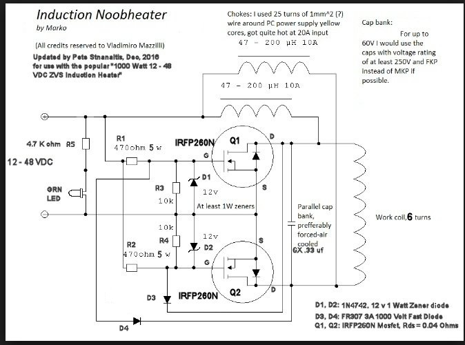 While all of this techy stuff can be interesting it likely makes very little sense to the guy who just wants to resize his brass and get good neck tension. I will add this. Circuits like this, designed for 12 Volts to say 48 Volts will not even start to oscillate at a voltage below 11 Volts. What happens is one MOSFET will start conducting, nothing will change state and it will die a horrible death. You want a power supply capable of at least 12 Volts and about 7 Amps to be on the safe side. Also, you never want to use a variable or adjustable supply and start with a voltage below 12 or 13 volts or bad things will happen. These circuits do work as off the boat from China but they are easily killed in a plum of smoke. This concludes my little off topic contribution, we can now resume gun stuff. Electrical engineering types with a fetish for guns worry me. </OffTopic> |
|
|
|
December 16, 2017, 09:35 PM
|
#24 |
|
Senior Member
Join Date: April 10, 2008
Location: Alaska
Posts: 7,014
|
Ok, granted we got off topic.
Unclenick: Can we get just an annealer group just for these twisted discussion? For sure there are people wandering around with a glazed look and that is dangerous, NOTE: Keep away from the reloading bench until you decompress! It was back about 1982 I got into the electrical world, more generators and switchgear as well as starters and motors, not a huge need to get deep into some areas (or I had enough on my plate) . So yes, it was E and I and R and then P when I needed to deal with generators and load banks and what was I pulling on that engine with a resistive load . Twinkle twinkle little star, E = I squared R. and all that. My UPS systems (rectifier/dc link/inverter) did have all that but it was a Sams guide sort of troubleshoot , waveforms and voltage levels correct until they were wrong or gone and then it was back to the previous testing point. they don't even have testing points anymore. We learned all that and then just changed out board (after we proved that was where the problem was) Also power supplies are not my forte. Now I know I am going off tangent, but if the power supply says 12 to 48 VDC, then should it not accommodate the 12? I do have sensors that will take 12 to 32 or some such, AC or DC. Some like cheap voltage seniors just use a heavy resisters to drop the voltage to a lower level (and they fail after 10 year) Transformers are more better but this is AC so you can do it with them.
__________________
Science and Facts are True whether you believe it or not |
|
|
|
December 16, 2017, 10:20 PM
|
#25 | ||||
|
Staff
Join Date: February 12, 2001
Location: DFW Area
Posts: 24,990
|
Quote:
Therefore, anytime one is dealing with non-zero voltage, there is resistance in the equation somewhere, even if it's not explicitly called out. Quote:
I = E/R Increase voltage with resistance remaining the same (because it's the same circuit) and current must also go up linearly. Since P = E * I, then we can substitute for I from the equation above. P = E * E/R = (E^2)/R Quote:
Quote:
It is true that there are devices which can alter their resistance to maintain a constant current output even when the voltage is varied. That's why there's the caveat that if there's current limiting circuitry things are slightly different. However, even in that case, you'll know when you get to the end of what the power supply can handle because the voltage won't adjust up any farther.
__________________
Do you know about the TEXAS State Rifle Association?
|
||||
|
|
|
|
|


