Quote:
|
For those of us not in the industry (and/or not in Q.C.), what is "tolerance stacking" and how does it apply to S&W revolvers?
|
Howdy
Tolerance stacking is a term used in all industries that manufacturer physical products. It is not related to the firearms industry alone.
Many people think CNC (Computer Numerical Control) equipment magically makes perfect parts. In another life I was a CNC operator, CNC programmer, and draftsman. I may be able to clear up some misunderstandings.
The first thing you have to understand is that no process, and no machinist, can make a perfect part, no matter how hard they try. When I say perfect, I mean a part that perfectly matches the dimensions.
I am going to only discuss old fashioned plus and minus tolerancing, I am not going to even venture near geometric dimensioning and tolerancing, which is what most companies are using today.
Here is a very simple part drawing. It is a simple block, ¼” thick, 1 ½” long and 1” wide, with a 5/8” hole drilled through it. The center of the hole is 1/2" from one side of the part and 1/2" from one end.
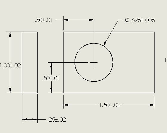
The numbers with the + - symbols are the tolerances.
Tolerances dictate how much variation from the perfect dimensions I will allow for my part. If I gave this drawing to a machinist with just the basic dimensions he will ask me what the tolerances are. The reason for this is that the more closely the actual part comes to the perfect dimensions on the drawing, the more expensive it is to make.
What this drawing is saying is that I will accept a part that is between 1.48” to 1.52” long, .98” to 1.2” wide, and .23 and .27 thick. In addition, the hole must be .620 to .630 in diameter, and it must be located .49 to .51 from one side and .49 to .51 from one end.
These are very, very loose tolerances. Part length, width, and thickness have a tolerance window of .040 each. That’s more than 1/32”. The position of the hole has a tolerance window of .020 in X and Y and the diameter of the hole has a tolerance window of .010. Fred Flintstone could make this part blindfolded and every part would pass incoming inspection. So no money would have been wasted making bad parts that did not meet the dimensions and tolerances called out in the drawing.
But tolerances do not come out of the thin air.
They usually are related to the dimensions of mating parts.
Just for the sake of argument, let’s say that a 5/8” diameter rod is going to go into that hole. If I dimension the diameter of the rod the same way, chances are it will not fit. If I tell the lathe operator to make me a rod that is .625 +/-.005 in diameter, he can certainly make them and I will have to accept every rod he makes from .620” to .630” in diameter. And I have accepted every plate with a hole from .620 to .630 in diameter.
A rod at the high end of the tolerance, .630, will not fit into a hole at the low end of the tolerance, .620 in diameter. So I will pay for a lot of parts that do not fit to each other, unless I want to pay my assemblers to mix and match until they find parts that fit each other. Not the way to go in mass production.
If I want to guarantee that all my rods will fit into all my holes, I will have to change the tolerances to something like .625 +.005/-.000 for the hole diameter and .624 +.000/-.004 for my rod diameter. So then I will accept holes between .625 and .630 in diameter and rods between .620 and .624 in diameter. There will be something between .001 and .010 of slop for the fit of the rod in the hole. This may or may not be acceptable, depending on the design concept of the parts. I may have to tighten the tolerances further, depending on the design concept of the assembly.
The rub is, I have just made my parts more expensive. My machinist will have to be more careful not spending his time making parts with holes too small. Any he makes with holes too small my incoming inspector can reject. The same is true of the rods. Any that come in too big will be rejected. So costs have gone up to make the parts, and the machine shop passes those costs on to me. And that is just the fit of a rod to a hole. We have not mentioned the .020 positional tolerance in both directions for the location of the hole. Depending on the design concept of the final assembly, we may need to tighten the tolerances of more dimensions.
That is what tolerance stackup is. We used to call it doing a tolerance study. You run the numbers to make sure the parts will fit together in the final assembly and function the way they are supposed to. Our part is incredibly simple. In the real world of manufacturing, parts are much more complex and there are usually many more dimensions that are related to the dimensions of mating parts. So lots of dimensions have to be carefully examined and toleranced. And usually, the more precise the parts are, the more they cost.
When I was in the design end of things, we routinely toleranced all our dimensions at +/-.005. That was pretty routine and any machine shop could meet those requirements. Of course, we were making fairly small parts, usually less than 1 foot long. Tolerances have to relate to the real world the parts live in. You are not going to tolerance the window openings in a commercial airliner at +/-.005.
What does all this have to do with CNC? Most CNC machines today are very precise. They can do +/-.002 without batting an eye (a sheet of paper is about .004 thick). But what does that really mean? A manual machinist who was turning the wheels on a Bridgeport took into account the backlash in the system. Meaning how much slop there was in the mechanism so the tables would move when he started turning the cranks (huge over simplification here).
CNC equipment does not defy the laws of physics. There will be a certain amount of slop for the X,Y tables and the quill in even the most expensive modern equipment. But most will use some sort of electronic feedback loop from the motors to allow for that. In other words, if the program tells the table to move 1.001", the feed motor will stop moving at 1.001. Tool wear is another thing. Over the life of an endmill, as it wears, the cut it makes will become narrower. I’m not sure how the most modern equipment allows for that, but there will be a process.
But the bottom line is, CNC equipment is not magical.
A great deal of manufacturing today is done directly from 3D CAD (Computer Aided Design) directly to the CNC machine. An engineer creates a 3D model of his part in his computer, and sends the file to the CNC programmer. The programmer still has to take that information and create the CNC program, it does not happen automatically. He will decide which operations are done first and which operations are done after that, he will choose tool diameters for certain cuts, he will determine spindle speeds and feed rates, and a bunch of other things. If he screws up any of these parts of the program, he may break a tool or he may turn out crap. And somewhere in his notes, or in the design, the engineer will have built his tolerances in.
Then there is the matter of fixturing. Our simple part could be made from one simple set up in a vice. A more complicated part may require several setups to complete it. Meaning you may have to pop it out of the vice and reposition it to cut features on another surface. Repositioning a part invites inaccuracy to creep into the part. Parts that are made over and over again will have specific fixtures made up for them, to hold the parts in various positions in the machine. Then, before the program is started the machine will be zeroed in X,Y, and Z to the new position of the part. The most modern Machining Centers may be able to pick up a part from one fixture and reposition it on another fixture, without the assistance of an operator, rezeroing before continuing, I don’t really know.
I had a conversation with an engineer from S&W a number of years ago mentioning the amount of precision their CNC equipment was capable of. I really don’t remember the numbers, but they were very precise, much better than +/-.002. It was down to a few ten thousandths of an inch.
But the machines are still not perfect. Parts still have to be designed and toleranced correctly or they will not fit or function as they are supposed to.
There are several reasons why CNC adds value to the production process. One operator (not as skilled as a good machinist) can operate several machines simultaneously. There is no human error that creeps into the parts, such as the machinist accidentally turning the cranks too far, the machine is programmed to move the tables the correct amount, and allow for any slop in the tables. And CNC equipment can generate complex curves, which could only be done on old milling machines by following patterns.
But machine precision still enters into the equation, no matter what, there will still be a tiny amount of variation from part to part. Whether or not the amount of variation is significant is another matter.
And parts still have to be designed correctly, or it will be garbage in, garbage out.
P.S. A few years ago I had a job as a technician in a start up that was making some pretty interesting electro-mechanical devices. One of my tasks was to build prototypes. Every time an engineering change was made to the parts, I would build up a few assemblies to make sure everything fit. I can't tell you the number of times I went to the design engineers to tell them what did not fit where. It all boiled down to manufacturing tolerances related to the types of materials the parts were made from.