
|
|
|||||||
| Forum Rules | Firearms Safety | Firearms Photos | Links | Library | Lost Password | Email Changes |
| Register | FAQ | Calendar | Today's Posts | Search |
 |
|
|
Thread Tools | Search this Thread |
 February 17, 2014, 08:23 PM
|
#1 |
|
Senior Member
Join Date: May 17, 2012
Posts: 1,085
|
Thoughts on Trigger Design...
This thread is to be in the same vein as the similarly-titled one on safeties. Rather than try to claim victory for one particular model (let alone brand) of trigger system, lets please limit discussion to the nitty-gritty of what makes certain trigger designs successful or desirable. I'm not against using examples like K31's or 1911's to describe good end products, but we're much more interested in what makes them good specifically, here
 Also, while not necessarily limited to such (this being the "general" forum, after all), I am personally most interested in hammer-fired semi-auto systems, since that is what I will have to design for the little 7.62x25 carbine I wish to build this year (the "Skorparev," see attached) Suggested routes of discussion to get things moving; -Movement types; are sliding, rolling, or pivoting motions best for trigger linkages or contact surfaces? -Sear placement; is it better to put the primary (firing) sear close to the pivot axis, or out at the tip? What about the secondary sear's position (if separate)? -Trigger motion; sliding, pivoting, or some combination of the two (rolling)? -Disconnectors; sliding (AR15), pivoting (AK), or something else? -Sear engagement angles; striking the best balance between safety and quality of trigger pull -Stacking/staging; the best way to add a light takeup stage before a crisp second stage release (how to do it; not whether it is superior to a single stage or not!) And of course, any off-the-wall or uncommon ideas you think might make for a good (mechanical) trigger that no one has had the stones to try yet! TCB
__________________
"I don't believe that the men of the distant past were any wiser than we are today. But it does seem that their science and technology were able to accomplish much grander things." -- Alex Rosewater |

|
|
February 18, 2014, 11:20 AM
|
#2 |
|
Moderator Emeritus
Join Date: April 27, 2013
Location: Ohio
Posts: 1,923
|
You might be better to post this at the Smithy part of the forum, where we're all at.
|
|
|
|
February 18, 2014, 02:14 PM
|
#3 |
|
Staff
Join Date: March 11, 2006
Location: Upper US
Posts: 28,832
|
Agreed! Moving to the Smithy..
__________________
All else being equal (and it almost never is) bigger bullets tend to work better. |
|
|
|
February 18, 2014, 04:27 PM
|
#4 |
|
Moderator Emeritus
Join Date: April 27, 2013
Location: Ohio
Posts: 1,923
|
There are numerous trigger designs, and which ones depends on what you want to do, whether general sporting, or precision target.
I like two-stage triggers, but that is for accuracy, and some may not like them. As far as firearms for general game hunting, and personal protection, one with a trigger pull of 3 to 4 pounds is okay for me, but then again, some might like others, especially at very long ranges. As far as a dependable rifle trigger/sear, the old Mauser design is one of the best. It can be described as a two-stage also, with no bells or whistles, as it works off cams machined into the trigger. It is simplicity at its best. If you want an adjustable trigger, there are several patented designs, such as Timney and others, but it is according to what you want, and the intended use. Edit: I wanted to add, if this is for a semi-auto, one of the best designs, holding with the kiss principle, is the two hook design of Browning, which has been used and modified extensively. This would be the one used in the Auto-5. For full auto, the disconnector hook can be made toggle on a spring loaded pivot on the trigger, and shoved back by a bolt cam, allowing the hammer to fall as soon as the bolt is closed, or using a hammer block. The M1 Garand in full and semi-auto is an example, along with the AR-15 (modified sear placement). For full auto only, firing from an open bolt is the most simple method. Here, a fixed firing pin is used, and when cocked, the bolt stays open. When the trigger is pulled, the mass of the bolt flying forward drives the firing pin into the primer. It simply runs until the trigger is released, or its out of ammo. Always use the kiss method (keep it simple stupid), I live by it. Browning Auto-5: 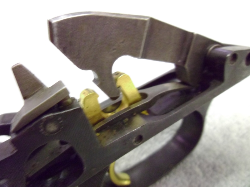 Auto-5_Trigger by matneyw, on Flickr M1:  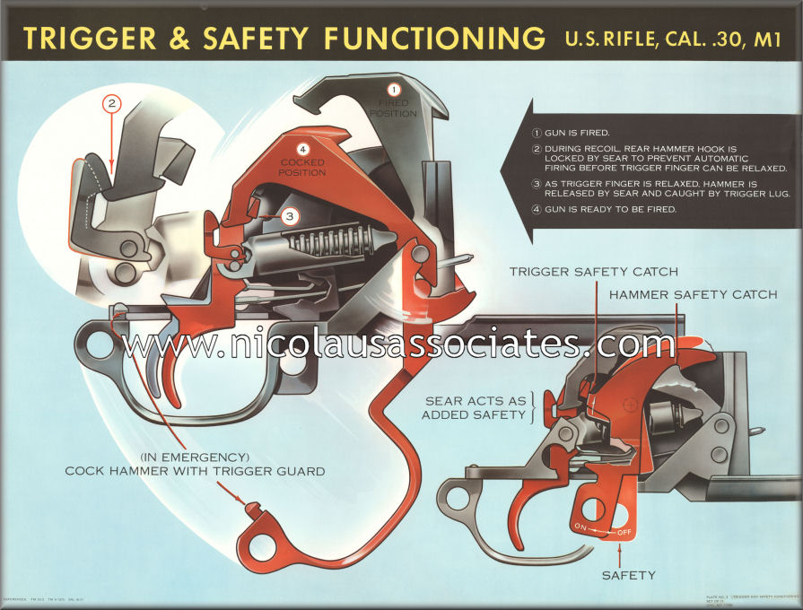 I consider this a bad design, it's a Rube Goldberg, so to speak. 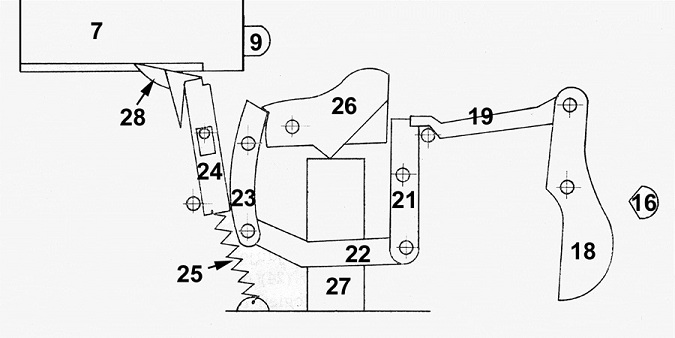
Last edited by Dixie Gunsmithing; February 19, 2014 at 03:39 PM. |
|
|
|
February 18, 2014, 11:07 PM
|
#5 |
|
Senior Member
Join Date: May 17, 2012
Posts: 1,085
|
Good thoughts, Dixie
 . I'm actually pretty familiar with the two FCG's you posted; I was actually going to use a Czech VZ52 trigger (identical to the M1) for my carbine project, but it's too big and doesn't fit well, and I'd hate to chop on something like that which isn't made anymore. The Browning design is pretty similar to what is in my FN49 (which Browning worked on before his death), and I've heard both are pretty reliable (and they both work fairly similarly, too). . I'm actually pretty familiar with the two FCG's you posted; I was actually going to use a Czech VZ52 trigger (identical to the M1) for my carbine project, but it's too big and doesn't fit well, and I'd hate to chop on something like that which isn't made anymore. The Browning design is pretty similar to what is in my FN49 (which Browning worked on before his death), and I've heard both are pretty reliable (and they both work fairly similarly, too).What's odd, is the M1 sear arrangement is very similar to the AKs, that is, two hooks at the tail end. An AR has two sear bents (grooves), but the primary one used to release the hammer is at the root of the hammer. Always seemed strange to me that an AR trigger should be better, since the closer you get to the pivot, the higher the stresses on the sear surface from the hammer spring; you'd think friction would go through the roof, as well as leverage if there is a negative sear engagement angle. But with the AR, the sear is much further from the trigger pivot (far forward near the hammer pivot) than the AK, whose sear is more or less right above the trigger. I can see that difference making the AK trigger longer and spongier, but only because of leverage, which would suggest it should then be lighter. I's confoozed.  The other issue I am curious about, is safety. That is, for a trigger of given weight, say 4lbs, what sear arrangements tend to "hold" the best during unintentional shocks and cycle vibrations? It may not depend on the sear at all for all I know, and instead fall onto whatever safety mechanism locks the hammer/trigger when the trigger is not depressed (if there is one). Related to this is avoiding an easy conversion to full automatic, more because the issue is closely related to reliability/safety, than the legal aspect (though I'm mindful of that, too). Does orienting the travel of a sliding disconnector in line with the bolt travel/recoil make it unsafe? If doing so would require a heavier spring to ensure its operation, that's obviously something to avoid if possible. Attached is the FCG idea I've whipped up for the Skorparev concept; the thinking was to keep the overall mechanism as short as possible, since I had plenty of room front to back the way the design worked out ('small as possible' is a major driving factor in the design). I currently have the trigger pivot far forward directly above the sear, but I am starting to think I should move it back to above the trigger, or even switch to a sliding trigger to cut down on the motion of the finger needed to release the hammer. Since I have the freedom to select the trigger motion I like, is it generally a good idea to drag the sear straight off the hammer, or drag it off at an angle so the hammer moves bit forward or backward? I am wondering if a positive engagement angle would keep the hammer safely secured with a short sear surface, while pulling it off so the hammer lets down just a fraction would negate the heavy/gritty trigger feel positive engagement usually causes as the sear 'climbs uphill' against the hammer spring before releasing. (Looking at it now, I'd also make the spring pushing the disconnector attach onto the trigger, so the disconnector engagement force does not fight the trigger return spring and force it to be heavier. If attached to the trigger, it could be set to place zero tension on the disconnector until the trigger is about to break) I don't suppose clock vs. coil springs have any impact on things, but I'm leaning toward a clock spring since AR/AK parts are common, cheap, and don't tend to launch projectiles across the room  . I also have a full 1" or so to work with on width, which is plenty for the portly AK and AR hammer spring designs. . I also have a full 1" or so to work with on width, which is plenty for the portly AK and AR hammer spring designs.I'm been staring at that Garand safety diagram for like five minutes, and I still can't see why my BM59 trigger group safety can't re-engage once it is released unless I manually press the hammer down all the way (I'm thinking the trigger must be interfering on the hammer somehow, and can't reset enough to let the trigger block rise, or the hammer block interface is barely too tight and won't mesh unless the hammer is fully depressed by the retracted bolt).BTW, what the heck is that last FCG? TNW's kludge solution for a Suomi hammer conversion, or something? TCB
__________________
"I don't believe that the men of the distant past were any wiser than we are today. But it does seem that their science and technology were able to accomplish much grander things." -- Alex Rosewater |
|
|
|
February 19, 2014, 11:03 AM
|
#6 |
|
Moderator Emeritus
Join Date: April 27, 2013
Location: Ohio
Posts: 1,923
|
What the reason is, with the Browning design being modified the way it has, is to skirt by patents, or to use in a selectable full auto arrangement. You can see this in the M1 Garand, the AK, and the AR-15 M-16, except Stoner moved the sear to the bottom of the hammer in the last, which will produce more wear, and a harder sear release over friction. All of them, on full auto, have a means of pushing back the disconnector hook, by the bolt, once its closed, or use a hammer block.
AR-15:  M-16:  As far as safety's, the easiest method is to simply block the trigger from being depressed. On the Browning A-5, the later model, He simply added a tang on the back of the trigger that would hit a cross bolt. These are also the easiest for the shooter to use, IMO, as the rotary style is harder, and you have to twist the thing to use it. However, they use this to select semi and full auto too, but that is not to say you can't have a selector lever and use a cross bolt safety with it. Browning also added a trigger block, operated off the bolts action link, so the trigger was blocked until the bolt closed. It is the toggling piece behind the trigger in the photo. I don't mention the first model, as it had the suicide safety and didn't have the trigger block. It was dangerous, as he had the safeties movement backwards. Another good safety was on the Winchester Model 12 and 25, as it simply blocked the sear arm of the trigger from moving down, and it was at the front of the trigger guard. This gun also includes a hammer block, so it can't fall until the bolt is closed. It also made the gun one of the fastest shooting pumps ever made, as it had what is known as slam-fire, where the the gun would fire as soon as it was wrenched closed, and the trigger held down. I have seen it fired as close to fast as a semi-auto. Of course, it was properly named the perfect repeater too. It has the same problem of sear pressure, though, as the AR-15, and several other guns, that have the sear at the bottom of the hammer. Winchester actually made this into a automatic prototype, but never went into manufacture, though did patent it. The Rube Goldberg design, I call it, was a drawing that showed up on Forgotten Weapons, and there is a reason why it is forgotten, its way too complicated IMO, which makes it easier to wear and fail. Last edited by Dixie Gunsmithing; February 19, 2014 at 03:01 PM. |
|
|
|
February 19, 2014, 12:56 PM
|
#7 |
|
Moderator Emeritus
Join Date: April 27, 2013
Location: Ohio
Posts: 1,923
|
I forgot to add, that the hooked trigger, by Browning, has a positive sear engagement, in that the hammer will go backwards a minute amount, when the trigger is pulled. The disconnector, though, you want it at neutral or slightly negative, so it will release when the finger comes off the trigger and against it's spring. However, the sear needs to be where it will completely seat, over the notch, before the disconnector finally releases.
The Rube gun is a Polish Beha SMG, which I didn't want to reveal fearing rude comments by others. 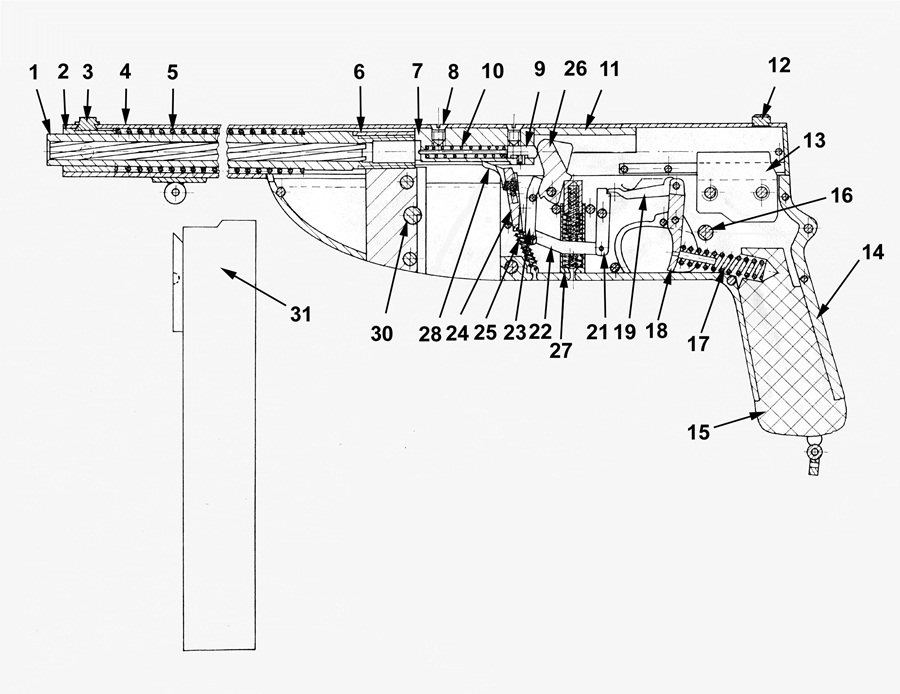 Addition: On hammer springs, coil springs will not break as often as wind-up or flat springs. They used a twisted two-pair music wire spring on the AK and some others over this. 
Last edited by Dixie Gunsmithing; February 19, 2014 at 05:21 PM. |
|
|
|
February 19, 2014, 05:59 PM
|
#8 |
|
Moderator Emeritus
Join Date: April 27, 2013
Location: Ohio
Posts: 1,923
|
On the Garand safety, below is a link to a video by the Army, with a cut-away animation on the operation. It does show the safety operation from the left side of the gun, and how it should mash the hammer back some.
M1 Garand: "Rifle US Caliber .30 M1 Principles of Operation" 1943 US Army: http://www.youtube.com/watch?v=wcoRgWLcbNE This is on the M-14, but it doesn't show much on the safety function, but is better on the trigger group. However, I never did agree with the Army calling the disconnector the sear. They call the actual sear hook the forward hook and lug. Though both hooks could be called a sear, they never get the difference correct. The disconnector could only be termed this in full auto. U.S. Rifle, Cal. 7.62MM M-14 Operation And Cycle Of Functioning (1960): http://www.youtube.com/watch?v=1Kgnh4neVaY Last edited by Dixie Gunsmithing; February 19, 2014 at 06:27 PM. |
|
|
|
February 19, 2014, 09:13 PM
|
#9 |
|
Senior Member
Join Date: May 17, 2012
Posts: 1,085
|
To be fair, the Beha was a closed bolt select fire, so a mere semi design would be about half as complex (the way he did it). Still a kludge, but not bad for a man who knew not what he was doing
.Regarding my BM59 safety, I think it just needs breaking in (unissued condition) and has a sharp edge that blocks the safety from sliding into the hammer. I'm loathe to take it apart since coil-spring hammer struts and I have an...icy relationship when it comes to reassembly (dis-assembly is always easy ).Perhaps interesting to note; both my AR70 and STGW57 triggers place the sears alongside each other in the same notch on an extra wide hammer near the pivot axis. I think you are onto something about that placement being hard on the sears; the AR70 sears are a good 1/8" across, the STGW57's nearly 1/2" wide  --no wearing that sucker out, ever! Both are decent triggers, the STGW poor by Swiss Standards but at least consistent. The AR70 is a good bit lighter than the VZ52 FCG but has more spongy takeup (and the BM59, but that one is still new and rough, as I mentioned) --no wearing that sucker out, ever! Both are decent triggers, the STGW poor by Swiss Standards but at least consistent. The AR70 is a good bit lighter than the VZ52 FCG but has more spongy takeup (and the BM59, but that one is still new and rough, as I mentioned)Attached is the FCG concept update, I've decided to go with a straight pull trigger for now. I think there are some easy ways I can get the trigger, hammer, and disconnector to sit alongside each other to make the overall length even shorter, but this setup is nice and two-dimensional (makes manufacture easier). I'm thinking I'd use a slot in the trigger and one roller to keep the pull nice. When cocked, the hammer contact will tilt the opposite end of the trigger into a recess (not a real safety, but may improve trigger stability in a drop and give that 'positive reset' everyone's so worried about), but the grip angle relative to the trigger will pull it up out of the notch, and then straight back, while contacting only the single roller and the sear within a narrow angle of rotation (pulling up or down will bottom the trigger out on stops). Seems like it'd be hard to get a much nicer pull than that if you use proper form and don't drag the trigger across the stops by pulling at a funky angle. The actual angle of the trigger surface could be easily adjusted to make matching that angle with the pull easy for a particular shooter, too. TCB
__________________
"I don't believe that the men of the distant past were any wiser than we are today. But it does seem that their science and technology were able to accomplish much grander things." -- Alex Rosewater |
|
|
|
February 19, 2014, 09:29 PM
|
#10 |
|
Moderator Emeritus
Join Date: April 27, 2013
Location: Ohio
Posts: 1,923
|
Actually, your last trigger design is a good idea, and may be patentable. I have not seen that used, and it might be best to say patent applied for, even if you haven't yet. I think that also covers the time it takes you to get the drawings to either a patent attorney, or to the Patent office, along with a working prototype. You can patent the trigger mechanism, and not the entire gun at first. That is why a lot of guns have several patents covering one model.
Also, according to the new patent law, if someone was to steal it, you can show our correspondence that you had the idea first, and still manufacture it, as you used to not be able to. I would make a model of it quickly if I were you. Now, the law says that if someone else had been using a design, before a patent was made by another, the one using it can still use it. It is one of the best changes in patent law in a very long time. |
|
|
|
February 19, 2014, 11:30 PM
|
#11 |
|
Senior Member
Join Date: May 17, 2012
Posts: 1,085
|
I really don't care, it's not like I'm gonna tool up and make/sell a hundred of these things. Who'd buy them? They won't fit in an AR!
Heck, that patent could be used as evidence to claim I'm making guns with the intent of selling them unlicensed. In any case, it'd be pretty easy for someone to work around something this simple, prove that it's been patented before, bury me with litigation if they cared to, or just steal the thing and allow me to bankrupt myself chasing them. Patents existed originally as a means to brand products in an age of consumer ignorance and rampant forgery. Like all laws 'banning' human activity, they never actually stopped or prevented anything. And we have the internet, now, to expose thieves and promote the original article. (we also have China, now )Far smarter and easier to not "put up your dukes" an invite the big boys to stomp you, and instead lay low and market the product word of mouth (or web) in narrow, isolated channels ignored by industry (again, not that I ever intend to  ) )Mostly, it's just more trouble than I'm willing to deal with for a simple lark; the finished gun will be reward enough, so I'm happy to share anything that helps others build guns for themselves successfully. Case in point: why no build section in the Gunsmithing forum? There's whole thriving websites with hundreds (okay, not thousands) of members dedicated to it.TCB
__________________
"I don't believe that the men of the distant past were any wiser than we are today. But it does seem that their science and technology were able to accomplish much grander things." -- Alex Rosewater |
|
|
|
February 20, 2014, 12:02 AM
|
#12 |
|
Moderator Emeritus
Join Date: April 27, 2013
Location: Ohio
Posts: 1,923
|
On this, since its a sliding design, you'll need it made so dirt wont foul it, or so it is self cleaning. Also, a cross bolt safety would be perfect for this.
You could get by without having a spring loaded disconnector here, to, as Browning didn't use it, and any perceived bounce in the trigger, I've never noticed when shooting one. You might in a full auto, but a semi-auto, I would say you would be okay, and its less moving parts. Then you would need just a trigger spring to push the group forward. That would really be taking a Browning trigger and sliding it instead of pivoting it. One last thing, before I forget, on the Garand pics above, is I think the one from the manual shows the sear angle wrong, but the disconnector is right or close. It shows the sear to be almost negative, and it is really positive. When you watch the video on the M-14, you will see them angled different, on the large model, and really, it uses about the same trigger group. Just disregard them calling the disconnector a sear, and of course they would never admit to being wrong.
|
|
|
|
February 20, 2014, 08:03 PM
|
#13 |
|
Senior Member
Join Date: May 17, 2012
Posts: 1,085
|
My thought is the lack of contact surfaces (just the pivot, sear ledge, and reset contact) and pivoting of the trigger will make the tolerances loose enough for junk to rattle out of the way. The pivot pin slot will be generous, since it only ever bears of one side of the track anyway (may just use an oversized hole, since I think trigger travel will only be .02" or so after the pivoting takeup)
I ran a few numbers today, trying to determine how sear friction would relate to trigger pressure in a setup like this. If the sear friction is too great, the trigger will not slide, and instead pivot upward until bottoming out on the housing. Too little, and it will drag on the opposite reset surface. Either will negatively affect pull. My calcs show that, for simple orthogonal sear/trigger force directions (up/down and forward/backward, respectively) the ratio of trigger length, where your finger sits, to sear length from the pivot, is equal to 1 divided by the coefficient of friction. For polished/oiled steel, it's something like .16. So, putting your finger ~1" from the pivot, means the sear must be about 3/16" out; easily doable. Hammer spring force is directly related to sear friction, which is equal to trigger pull weight (plus the return spring). I still need to run the numbers to find what force the hammer needs to get the velocity required to set off a primer, since that will set the hammer length and spring torque, which will then set the trigger weight, minus whatever reset spring weight is needed to overcome the disconnector. Kinda complex, shouldn't be too bad once I get it all on paper. TCB
__________________
"I don't believe that the men of the distant past were any wiser than we are today. But it does seem that their science and technology were able to accomplish much grander things." -- Alex Rosewater |
|
|
|
February 20, 2014, 08:11 PM
|
#14 |
|
Member In Memoriam
Join Date: March 17, 1999
Posts: 24,383
|
I don't have the time to go into a lot of detail, but in the M16 diagram, things don't work exactly that way. The bolt carrier is not shown, and understanding its role is essential to understanding that system.
Jim |
|
|
|
February 20, 2014, 10:58 PM
|
#15 |
|
Moderator Emeritus
Join Date: April 27, 2013
Location: Ohio
Posts: 1,923
|
James,
Yes, it doesn't make it clear where the bolt carrier should toggle the hammer block, how the selector moves it away for semi-auto, or show where the bolt hits in cocking, and it really doesn't look right, but was the only two animations I saw for this, when looking. I'm not for sure who did those, as I got the links through Google images, but they look to be from a 2D view of a 3D model, or maybe something done in a 2D cad, and then animated. That has had everything stripped away, but what little is shown. I hope it is plain enough, though, in what a hammer block does in full auto, and at least the semi-auto portion as well. It would have been nice to have shown the selector lever movement, etc. |
|
|
|
February 20, 2014, 11:49 PM
|
#16 |
|
Moderator Emeritus
Join Date: April 27, 2013
Location: Ohio
Posts: 1,923
|
Below is two YouTube videos on the M-16, showing the hammer block (auto-sear) operation, and how the selector cams it back on semi-auto, and allows the disconnector to work. Funny how they call it a disconnector here, and call it a sear in the Garand and M-14, confusing isn't it? Really, its dual purpose on the two guns, first its a disconnector, and second its used as an auto-sear.
I call the auto-sear a hammer block, as it was the old terminology for it, years prior, on other pump, semi, and full auto guns. I use it because it is easier to describe what it does, block the hammer from falling until the bolt closes. The term, sear, is really the term for the engaging surface, or edge of a piece, that holds a hammer back, or a piece that its sole purpose is to hold the hammer back which the trigger actuates for firing. For a disconnector, it is a piece that has a sear edge, or engaging surface, which is used to create a semi-auto function or action. How the M16 trigger works compared to the AR15 M-16 Rifle M16 Training Film: Rifle XM16E1 Operation . |
|
|
|
February 21, 2014, 12:56 PM
|
#17 |
|
Moderator Emeritus
Join Date: April 27, 2013
Location: Ohio
Posts: 1,923
|
I found the below video, which is an animation of the AK47, and shows how the bolt block, or auto sear works in it. I took the two still pics out of the video, and added the descriptions.
Video: AK47 Action Video Bolt Block engaged.  AKBB-1 by matneyw, on Flickr Bolt Block disengaged.  AKBB-2 by matneyw, on Flickr |
|
|
|
February 21, 2014, 02:28 PM
|
#18 |
|
Member In Memoriam
Join Date: March 17, 1999
Posts: 24,383
|
Much better. Many follks think that auto fire is achieved simply by letting the hammer follow the bolt down, something that is, at best, unreliable, and at worst can allow the gun to fire with the bolt unlocked, wrecking the gun.*
Except in blowback pistol-caliber weapons, a FA firearm has to have a means of making sure the bolt is fully locked before releasing the sear. In both the M16 and the AK-47, that is done by having the bolt carrier release the auto sear as it makes the final closing movement after the bolt is locked. The details are a bit different, but the essentials are the same. *I have heard dozens of stories about how some father or uncle or cousin in WWII "filed down the trigger" of his M1 rifle and mowed down 50 or 100 or 1000 Germans or Japanese with his improvised machine gun. And usually he told the sergeant or lieutenant or general about his idea and they court-martialed or promoted him or ordered him not to tell anyone or classified the idea top secret or ..... You get the picture. Jim |
|
|
|
February 21, 2014, 04:07 PM
|
#19 |
|
Moderator Emeritus
Join Date: April 27, 2013
Location: Ohio
Posts: 1,923
|
James,
The worst is, that kind of stuff is spread on the movies and TV. Remember MacGyver? One good thing did come from that show, it helped the duct tape manufacturers make millions. I am not aware of any closed bolt MG, that doesn't either use a toggled disconnector, or a hammer block/auto sear, even the Ma Deuce. Similar methods can be used to control a striker fired gun also. The first gun, that comes to mind, with a hammer block to keep the hammer down until the bolt is closed, is the model 12 Winchester. I wouldn't doubt that this could be one of or the earliest version of it. I don't think the Browning 1895 potato digger had anything like it, and not until the Browning Auto-5's trigger block and the Winchester model 12's hammer block, can I think of anything. Vickers, maybe, but I can't think of one. I think the Auto-5 and the model 12 are the two guns that gave everyone the idea after they came out. Actually, the Auto-5 never came out with that trigger block until later on, and I don't think it was ever in the Remington model 8 rifle. The Winchester model 11 just blocked the firing pin if I remember, and the 1907 and 1910 rifle didn't have it either, that I can think of. |
|
|
|
February 24, 2014, 09:35 PM
|
#20 |
|
Senior Member
Join Date: May 17, 2012
Posts: 1,085
|
Bringing this back to semi-auto design, attached is the updated-est concept. The disconnector now goes around the side of the hammer as opposed to beneath it (makes things shorter while keeping the part a simple folded sheet metal piece). It is now returned by an independent spring, I just couldn't stomach the thought of intentional trigger slap (that stuff's for the Tac-Con crowd
) so I split it off into a separate piece, probably a leaf spring, possibly an extension of the hammer-spring tail if it isn't stupid-strong.The hammer is simplified a bit, it now has a rough "f" shape, the upper front leg the sear, the lower front leg the pivot contact surface, the rear leg the spring-arm (also slips over the 'reset ledge' as I'm calling it now). The trigger spring could possibly be an extension of the other hammer spring tail (it's a dual-coil AR/AK type) to simplify the number of parts further. The front of the trigger is now what pushes on the disconnector, which when pushed off the hammer, does not contact the trigger for the majority of the pull. I also added in the grip safety mechanism, a very simple cross-bolt type which slides off either side of the trigger arm to allow it to move back. It will actually extend out the sides of the grip slightly and be returned to center by a spring, the lowest digit of the trigger finger will push it clear of the trigger as the fingertip is laid onto the trigger. Another part of the safety piece will deactivate one of two ejectors, causing the spent cases to eject out the desired side (based on grip hand) automatically A separate manual safety, I'm thinking tang at this point for ambidexterity and narrow width considerations, will slide over an extension of the hammer sear surface to lock the hammer, and will also engage the grip safety to fix it in the center and block the trigger. Very secure, and keeps a non-locked trigger sear from being able to slide back and forth across the bent on the locked hammer, damaging the sear faces. This safety will sit at the front of the grip cut in the spine of the stock, protruding slightly into the webbing of the hand when locking the gun. TCB
__________________
"I don't believe that the men of the distant past were any wiser than we are today. But it does seem that their science and technology were able to accomplish much grander things." -- Alex Rosewater |
|
|
|
February 26, 2014, 02:45 PM
|
#21 |
|
Moderator Emeritus
Join Date: April 27, 2013
Location: Ohio
Posts: 1,923
|
barnbwt,
The only thing I would look hard at, with what you're wanting to do, is the hammer spring. If you could use a strut, attached to the hammer, and use a coil spring, I think you would have a much better and tougher design against spring failure. |
|
|
|
May 21, 2014, 05:42 PM
|
#22 |
|
Senior Member
Join Date: May 17, 2012
Posts: 1,085
|
I'm reviving this thread since I finally got around to making a proof of concept a few weeks back, but forgot to update here. Does pretty much what I was hoping; a two stage trigger with pivoting first stage and sliding second. It's worth noting, that even with a hammer spring as stiff as my S&W's, the pull is about 3lbs if done right.
 On that note, this trigger feels very different from anything I've messed with. It's a two stage, but without anything mechanically pegging the pivot to the slide off the sear, the staging is set solely by the user. If you pull back with a more upward vector, you increase trigger travel before the break, if you pull straight back, the break occurs once the trigger tail slips out of the recess (yielding a very nasty feeling trigger), if you pull down, the tail hits the recess and will not move*. If you stage the trigger just right, there's about a 1/16" movement of your finger to get the tail out of the recess, then it's a mere .05" further to pull the sear surfaces apart. In practice, with good materials, I think the travel could be half that, and with good polishing, the trigger pull below three pounds (perhaps much lower). It would feel weird to a new user accustomed to dual-stage triggers that divide stages automatically; this one's more like a manual transmission where you get to decide exactly how you want the trigger to roll over on the fly, and with practice, exactly how you want it. Not sure yet if that's a useful thing or not, but I find the idea interesting, at least. The engagement is huge because this is aluminum and I don't want it to wear out right away. Still, I'm impressed by a 3lb smooth (if perceptible in length) break off the sear hooks considering aluminum galls terribly, and these parts were all made with hacksaw/file and aren't even polished. A few points remain; -Most obvious is the disconnector, which will slide/pivot in such a way that it snags the second sear hook with the trigger pulled. It will also have the important function of blocking the trigger's return into the recesses before the hammer swings back, because such a scenario would crush the sear surfaces between the hammer pivot and the trigger-tail recess. -Spring layout for the trigger obviously needs to be fleshed out. The design is incredibly sensitive to force vectors, so placement and orientation of the spring has a huge impact on take up weight/length, and feel of the breaking stage. Might be fertile ground for experimentation, honestly. -Over travel adjustment needs to be added so the user's skill isn't quite so critical to function. Presently, pulling at the tip of the (shortened) trigger will cause the tail to rise way too far internally, causing the 'nub' on the trigger lever* to hit the stop before the sear releases. An overtravel lever at the very tip of the trigger would prevent over-rotation before break, without stopping the trigger cold (it would pivot backward around the over-travel stop until the sear break, and then the "real" trigger stop supplied by the nub) -*Design of the trigger safety setup, which will alternately block the nub on the back of the trigger lever. That's a simple swinging lever, and will wait for a later date, though. I am also considering incorporating the recess into the grip safety design, so the recess surface blocking straight-back travel drops away or something when the gun is gripped correctly (or a mechanical safety turned off) TCB
__________________
"I don't believe that the men of the distant past were any wiser than we are today. But it does seem that their science and technology were able to accomplish much grander things." -- Alex Rosewater |
|
|
|
May 21, 2014, 05:47 PM
|
#23 |
|
Senior Member
Join Date: May 17, 2012
Posts: 1,085
|
In belated response to Dixie; a coil spring + strut would be more reliable, but I just don't see any possible way to accommodate it in the particular gun design I'm working on. The trigger finger is right below the hammer tail, the magazine well right in front of the hammer pivot, and a mag release below the hammer pivot
 . Next time, though, I agree it'd be a more robust solution, but it'd still be tough with the disconnector sitting right where the strut would need to be (the disco would have to straddle it). . Next time, though, I agree it'd be a more robust solution, but it'd still be tough with the disconnector sitting right where the strut would need to be (the disco would have to straddle it).I suppose a hammer strut facing forward driving a lug on the bottom of the hammer might work, though (if you don't have a mag well in the way) TCB
__________________
"I don't believe that the men of the distant past were any wiser than we are today. But it does seem that their science and technology were able to accomplish much grander things." -- Alex Rosewater |
|
|
|
|
|


